
4 Key Gear Manufacturing Processes Explained
1. Introduction
In agricultural machinery, heavy truck, construction equipment and electric vehicle, gears must do much more than simply rotate. They need to carry high torque, run for long hours, and keep their accuracy over the whole service life. Whether a gear can do this reliably does not depend only on the drawing—it depends heavily on how it is manufactured.
As a precision gear manufacturer and custom gear supplier, PairGears combines modern machinery, controlled processes and experienced technicians to produce gears and shafts for demanding driveline programs. This article gives a clear overview of four core gear manufacturing processes: gear cutting, gear forming, gear grinding and heat treatment.
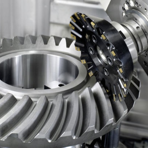
2. Gear Cutting: Turning Blanks Into Teeth
Gear cutting converts round blanks into parts with defined tooth geometry. Any serious error at this stage will follow the gear through the rest of the process, so method selection and process control are critical. PairGears mainly uses three cutting approaches.
2.1 Gear Hobbing
Gear hobbing uses a specialised cutting tool called a hob that rotates in a set relationship with the gear blank to generate the tooth form.
-Suitable for spur gears and some worm gears
-High productivity and good accuracy for series production
-Well suited to agricultural gearboxes, truck transmissions and construction equipment reducers

2.2 Gear Milling
Gear milling uses rotating form cutters to remove material from each tooth space.
-Flexible for small batches, prototypes and special modules
-Useful when geometry or lead time does not justify dedicated hobs
-Often used by PairGears in development and pilot builds
2.3 Broaching
Broaching uses a long tool with progressively deeper cutting teeth to form the full profile in a single stroke.
-Ideal for internal gears, splines and clutch teeth
-High repeatability once tooling is set up
-Applied at PairGears for synchronizer hubs and internal gear forms that demand consistent accuracy

The goal of gear cutting is to create a robust base tooth geometry with controlled stock allowance for heat treatment and finishing.
3. Gear Forming: Building the Right Blank
Before tooth cutting, the gear blank must be formed with the correct shape and internal structure. PairGears mainly relies on forging and casting, choosing the route according to load level, size and cost targets.
3.1 Forged Gear Blanks
Forging heats the metal to a plastic state and then presses it into shape using dies or forging tools.
-Produces favourable grain flow that follows the gear contour
-Improves strength, impact resistance and fatigue life
-Provides dense material with fewer internal defects
PairGears uses forged blanks for highly stressed gears such as truck ring-and-pinion sets, agricultural differential gears and construction machinery drive gears.

3.2 Cast Gear Blanks
Casting pours molten metal into a mould and lets it solidify into the required form.
-Allows complex shapes and large diameters
-Can be cost-effective for certain gear sizes and load ranges
-Typically requires additional machining and careful quality control
For moderate-duty applications and large components where forging is less economical, PairGears may use cast blanks combined with suitable heat treatment and machining to meet performance targets.

4. Gear Grinding: Achieving Precision and Smooth Running
Precision is critical in gear and spline manufacturing. After cutting and heat treatment, residual shape and surface errors can still affect torque transfer, noise and efficiency. Gear grinding is used to refine tooth geometry and surface finish.
4.1 Cylindrical Grinding
-Cylindrical grinding uses external or internal grinding wheels to finish diameters and bores.
-Controls fits and runout between teeth and reference surfaces
-Ensures that bearing seats, pilot diameters and bores meet tight tolerances

4.2 Tooth Profile and Lead Grinding
Profile and lead grinding uses specialised gear grinding machines and dressed wheels to finish the actual tooth flanks.
-Corrects profile and lead deviations left by cutting and heat treatment
-Enables controlled profile and lead modifications (crowning, end relief)
-Improves contact pattern, lowers noise and stabilises torque transfer
For heavy truck gears, EV reduction gears and quiet agricultural or construction drives, PairGears uses grinding to reach the required gear quality class and noise level.

5. Heat Treatment: Strength, Hardness and Life
Gears must not only be accurate; they must also resist wear, pitting and bending fatigue under real loads. Heat treatment tailors hardness and toughness to the application. Two processes are especially important for gears.
5.1 Carburizing
-Carburizing introduces carbon into the surface layer of alloy steel gears by heating them in a carbon-rich atmosphere.
-Creates a hard, wear-resistant case while keeping the core tougher
-Improves resistance to pitting, scuffing and surface fatigue
Common for high-load, long-life gears in truck axles, agricultural gearboxes and construction equipment

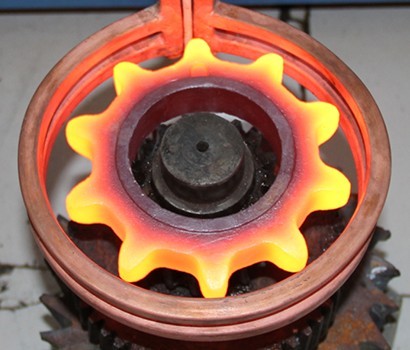
5.2 Quenching and Related Processes
Quenching rapidly cools the heated gear in oil, polymer or water to lock in the desired microstructure.
-Typically follows carburizing or other hardening processes
-Delivers the final hardness profile across case and core
-Requires distortion control and post-quench machining plans
Induction hardening and through hardening (quench-and-temper) are also used where local hardening or uniform properties are needed, for example on shafts or medium-load gears. PairGears integrates heat treatment design with material selection, geometry and finishing processes from the beginning of each project.
6. Process Overview
To make the four processes easier to compare, the table below links each step to what it delivers for real applications.
| Process | Main function | PairGears focus | Customer benefit |
| Gear cutting | Create basic tooth geometry | Hobbing, milling, broaching with set tolerances | Consistent teeth, controlled cost and lead time |
| Gear forming | Define blank shape and internal structure | Forged and cast blanks matched to duty | Strength and fatigue life aligned with load |
| Gear grinding | Refine tooth accuracy and surface finish | Cylindrical and profile/lead grinding | Lower noise, smoother meshing, better efficiency |
Heat treatment | Achieve required hardness and toughness | Carburizing, quenching, induction, Q&T | Long service life with resistance to wear and fatigue |
For each agricultural, truck, construction or EV program, PairGears configures these steps as a process chain that fits the torque, speed, life and cost targets instead of using a one-size-fits-all route.
7. A Typical Gear Manufacturing Flow at PairGears
For a heavy truck axle ring gear, a simplified process flow may look like this:
Engineering review – drawing and requirement review, material and heat treatment choice, accuracy class and inspection plan.
Blank forming – forging the blank, pre-machining reference surfaces.
Gear cutting – hobbing the teeth to a controlled pre-grind condition.
Heat treatment – carburizing, quenching and tempering with distortion control.
Finish machining – grinding datums and bores, grinding tooth profile and lead.
Inspection and validation – checking tooth profile, lead, runout, contact pattern, hardness and metallography.
Packing and shipping – marking, rust protection and packaging for transport.
Different products follow variations of this scheme, but the logic is the same: first secure the material and microstructure, then control geometry and surface condition to match the real application.

8. Conclusion
The four core gear manufacturing processes—cutting, forming, grinding and heat treatment—each control a different part of gear performance. When they are aligned, the result is a gear that delivers stable torque transfer, predictable wear and long life in real machines.
As a precision gear manufacturer and custom gear supplier, PairGears does not only quote drawings. We review duty cycles, choose suitable materials and heat treatments, and configure the right manufacturing route to support your life and cost targets.
If you are planning a new gearbox, axle or reducer, looking to improve gear life or searching for a partner who can review not only the drawing but also the manufacturing route, Contact Us to share your drawings, samples and operating conditions, and we will help you build a gear manufacturing plan that fits your application.
FAQ
Q1: What are the four main gear manufacturing processes described in this article?
A: The article focuses on gear cutting, gear forming (forging and casting), gear grinding and heat treatment. Together they form the core process chain PairGears uses to produce reliable gears.
Q2: Why is gear cutting considered the starting point for quality?
A: Gear cutting defines the basic tooth geometry and stock allowance for later steps. If the tooth form, runout or allowances are wrong at this stage, grinding and heat treatment cannot fully recover performance or consistency.
Q3: When should forged blanks be chosen instead of cast blanks?
A: Forged blanks are preferred for highly loaded, long-life gears such as ring and pinion sets and differential gears because they offer better grain flow and fatigue strength. Cast blanks may be suitable for moderate loads or very large, complex shapes when combined with proper heat treatment and inspection.
Q4: Why is gear grinding needed after cutting and heat treatment?
A: Cutting and heat treatment can leave profile, lead and surface deviations that affect contact pattern, noise and efficiency. Gear grinding corrects these deviations, applies fine modifications and produces the surface finish needed for smooth, quiet torque transfer.
Q5: What role does heat treatment play in gear performance?
A: Heat treatment sets the hardness and toughness profile of the gear. Processes such as carburizing and quenching create a hard, wear-resistant case with a tougher core, improving resistance to pitting, scuffing and bending fatigue so gears can meet their target life in real service.

