
Gear Milling vs Gear Grinding: What's the Difference?
1.introduction
Selecting between gear grinding and gear milling is not simply a matter of picking a machine. It is a process-route decision that affects dimensional stability, inspection strategy, cost structure, and delivery confidence—especially when the gear is heat treated or when tolerance windows are tight.
PairGears works with customers across four core sectors—Agricultural Machinery, Heavy Trucks, Construction Equipment, and Electric Drive systems—helping teams choose process routes that meet drawing requirements while staying realistic on cost and lead time.
This guide compares gear grinding and gear milling in a practical way: what each process is designed to do, where it fits best, and what information you should include in an RFQ to get a correct route recommendation early.
2. What each Process Is Designed to Do
Gear Grinding
Gear grinding is commonly used to refine gear tooth geometry and improve surface condition by removing a small amount of material with a grinding wheel. In many routes, grinding is applied after earlier machining steps and frequently after heat treatment, when the goal is to "bring the gear back" into the target geometry window.
Grinding is often selected when you need:
-Tight control of tooth geometry (profile/lead consistency)
-Stable, repeatable results batch-to-batch
-Final correction after heat-treat distortion
-Improved surface condition where specified on the drawing
Importantly, grinding is not always the only way to meet tight requirements, but it is a common and proven method for final refinement when other steps cannot comfortably hit the tolerance window.

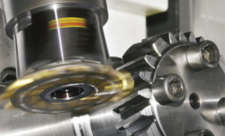
Gear Milling
Gear milling is a cutting process that uses a rotating multi-tooth cutter to generate gear teeth by removing material. Milling is widely applied because it is flexible: it adapts to different gear designs, sizes, and production constraints, and can be cost-effective depending on batch size and complexity.
Milling is often selected when you need:
-Broad capability across gear designs and sizes
-Efficient machining for many production scenarios
-Route flexibility for design changes or rapid iterations
-A cost structure that makes sense for prototypes, small batches, or certain steady volumes
Milling is not automatically "lower accuracy" It can produce highly accurate gears, but the process window depends more on tooling, setup control, and inspection closure.

3. Practical Fit by Gear Type and Geometry Access
A frequent misconception is that the gear type alone determines the best process. In reality, access and final targets matter more than labels.
Gear Grinding
Most commonly applied to external gears as a finishing operation
Especially relevant where final correction is needed after heat treatment
Feasibility depends on geometry access, tooth form, and process planning

Gear Milling
Applicable to a wide range of gear forms and sizes
Useful when the program benefits from process flexibility
Tooling selection and setup strategy strongly influence results

4. Heat Treatment Changes the Decision
Heat treatment improves gear performance, but it also introduces distortion risk. That means the“best" process before heat treat may not be sufficient after heat treat.
If your program includes carburizing or other hardening methods and you still need tight final geometry, the route often benefits from a finishing step that can correct post-treat variation.
If the gear is not heat treated, or if tolerance requirements are moderate, milling may meet requirements with a simpler route.
This is why process selection should be linked to:
The gear's final material state (soft vs hardened)
The drawing's inspection method and tolerance stack
The program's acceptance criteria and functional targets
5.Gear Grinding vs. Gear Milling
| Decision Factor | Gear Grinding | Gear Milling |
Final tooth geometry control | Tight final control is required, especially after distortion | Accurate geometry is needed with flexible route planning |
Surface condition (as specified) | A refined surface is required as a finishing step | Surface depends on cutter condition and cutting parameters |
Hardened gear finishing | Final correction/finishing on hardened gears is needed | Hard cutting may be possible but can raise tooling burden |
| Cost structure | Higher process cost is justified by final targets | Often cost-effective depending on volume/complexity |
| Lead time planning | Quality stabilization and predictability are priority | Route flexibility and iteration speed are priority |
| Risk management | Lower risk when tolerance windows are very tight | Lower risk when design changes or broader windows exist |
A short way to read the table:
Grinding is commonly selected to stabilize final quality.
Milling is commonly selected to build flexibility and efficiency into the route.

6. A Simple Selection Checklist
The fastest way to avoid wrong quotes and wrong routes is to provide the information that actually drives manufacturing decisions. PairGears typically starts with:
1.Gear type + application context
Example: transmission gear, differential gear, reduction gear, industrial drive gear.
2.Material specification
Include grade, cleanliness requirements if relevant, and any special metallurgical notes.
3.Heat treatment and final hardness
Carburized? Induction hardened? Quenched and tempered? Include hardness range and case depth where applicable.
4.Tolerance and inspection targets
Specify what truly matters: profile/lead/runout/pitch and the inspection method or standard if required.
5.Production volume and ramp plan
Prototype, pilot batch, steady production, annual demand—this impacts tooling logic and cost.
6.Priority statement
Example: “We prioritize delivery speed for prototypes” or “We prioritize stable geometry at scale.”
With those inputs, a supplier can recommend a route that is technically correct and commercially realistic.
7.Logic optimization
Rather than debating "grinding vs milling" as opposites, many successful programs treat them as complementary tools.
Common logic patterns
1.Use a cutting method (such as milling) to generate teeth efficiently and flexibly.
2.Apply finishing (such as grinding) when the final geometry window is tight, especially after heat treatment.
3.Close the loop with inspection: the process route must match how the part will be measured and accepted.
A robust process route is one that:
-Meets drawing targets consistently
-Is stable over tooling life
-Has an inspection plan aligned with the tolerance drivers
-Makes sense for the production volume and lead time expectation

8. PairGears Focus: Four Key Application Sectors
PairGears supports custom gears and gear sets for programs where reliability and consistent manufacturing matter:
8.1 Agricultural Machinery
Gears often operate under variable load and mixed duty cycles. Process planning typically balances durability, cost, and practical inspection targets.
8.2 Heavy Truck
Transmission and driveline components often demand stable batch performance and consistent geometry over long service cycles. Route stability and controllable variation become central.
8.3 Construction Equipment
Shock loads and harsh operating conditions make reliability the dominant theme. Process selection tends to prioritize repeatability and conservative risk control.
8.4 Electric Drive System
Depending on program targets, tighter geometric control can be required. Selection is driven by tolerance windows, heat treatment strategy, and inspection acceptance criteria.
Across all four sectors, the best route is the one that your supplier can deliver repeatably, not just once.
9. Quality Perspective
Whether the route includes milling, grinding, or both, the practical goal is consistent conformance to the drawing. Typical controls include:
-Tooth geometry verification (profile/lead), pitch consistency, and runout control
-Surface condition checks where specified
-Post-heat-treat distortion management aligned with final inspection criteria
For OEM programs, it is worth aligning early on:
-What will be measured
-How it will be measured
-What constitutes acceptance
-How variation will be managed through production
10.Conclusion
Gear grinding is commonly selected as a finishing step when tight final tooth geometry control and refined surface condition are required—especially after heat treatment. Gear milling is a versatile cutting approach that supports a broad range of gear designs and can be cost-effective depending on volume and complexity.
The right choice depends on your tolerance targets, heat-treat state, production plan, inspection method, and cost/lead-time priorities—not on process reputation.you can Contact Us to share your drawing, PairGears can provide a practical process-route recommendation and DFM feedback for your program.
FAQ
1. Is grinding always better than milling?
No. Grinding is often used for final refinement, while milling offers flexibility and efficient tooth generation. The “better” choice depends on requirements.
2. Can milling achieve high accuracy?
Yes, but outcomes depend on tooling, setup control, and the tolerance window required. Inspection alignment is key.
3. When does grinding become more important?
Often when the gear is hardened and you need final correction to meet tight geometry targets.
4. What should I include to get a fast, correct quote?
Drawing + material + heat treatment + tolerance/inspection targets + expected volume + lead-time expectation.

