Gear PCD Formula Measurement and Common Mistakes
Introduction
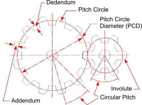
Gear PCD is one of those terms that looks simple on a drawing but causes real confusion in production and replacement work. Many buyers treat it like the outside diameter because that is the easiest size to measure. Others try to check it directly with a caliper. The problem is that PCD is not a visible edge on the gear. It is a reference circle used to describe where the teeth are supposed to work together.
At PairGears, we manufacture custom precision gears and gear sets for Agricultural Machinery, Heavy Trucks, Construction Equipment, and EV drivetrains. In real projects, a wrong pitch circle diameter can lead to wrong center distance, poor tooth contact, abnormal noise, tight running, or early wear. This guide explains what gear PCD means, how it is calculated, how it is checked in practice, and which mistakes buyers should avoid before moving into production or replacement sourcing.
What is gear PCD?
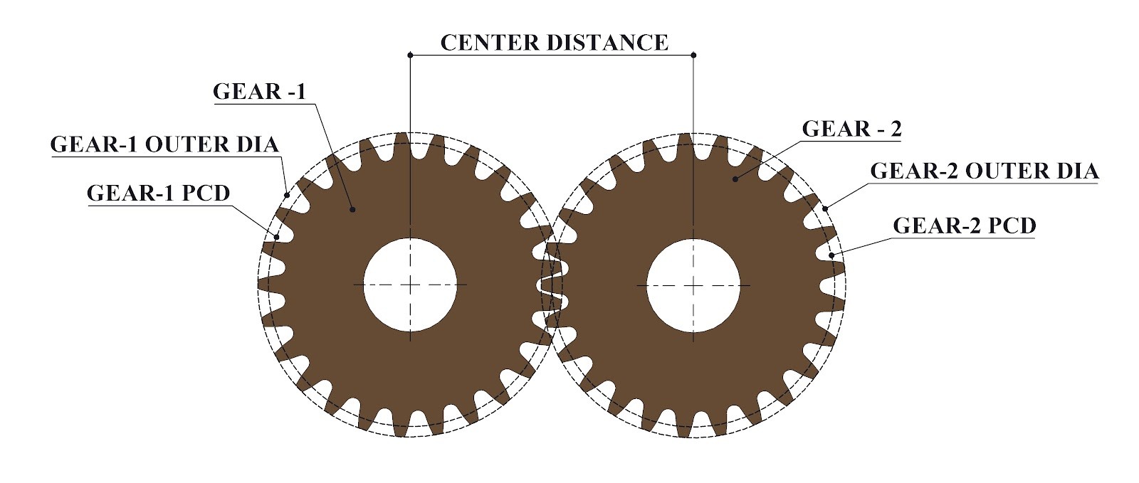
Gear PCD, or pitch circle diameter, is the diameter of the theoretical circle where gear teeth are assumed to mesh and transfer motion.
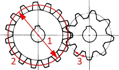
1. Pitch circle diameter (d)
2. Pitch circle (πd)
3. Circular pitch (πd / z)
Why gear PCD matters in real projects
PCD matters because it directly affects center distance. When two gears mesh, their pitch circles define the working distance between the gear centers. If the PCD is wrong, the gears may still look close in size, but the actual meshing condition will be wrong. That can lead to tight running, unstable backlash, edge contact, or noisy operation.
PCD also matters because it is closely linked to tooth size and ratio. It works together with tooth count, module, diametral pitch, and circular pitch. If one of these values is wrong, the rest of the gear geometry usually shifts with it. In other words, PCD is not an isolated number. It sits in the middle of the full tooth system.
For replacement work, PCD is often the difference between a part that fits the space and a part that actually works. An old gear may have the same outside diameter as a new sample, but if the tooth count, module, or pitch diameter is different, the set may still fail in service. That is why PCD review is especially important in OEM-number replacement projects, sample-based development, and cross-checking old worn parts.
The main ways gear PCD is defined or checked
| Method | What it uses | Where it helps most | Main caution |
| Direct formula from module | Module × tooth count | Standard metric gear projects | Must confirm the module is correct |
| Formula from diametral pitch | Tooth count ÷ DP | Inch-based gear projects | Metric and inch systems must not be mixed |
| Formula from circular pitch | Teeth × circular pitch ÷ π | Projects with pitch-based data | Circular pitch must be confirmed clearly |
Reverse estimation from OD | Outside diameter + tooth count | Sample-based or replacement work | Only an estimate for standard gears |
Center distance cross-check | Mating gear data + shaft spacing | Assembly review and replacement matching | Needs correct mating-part information |
Metrology / over-pin method | Pins, balls, or gear measurement equipment | Precision inspection and validation | Requires the right setup and interpretation |
For most standard metric spur gears, PCD is calculated by:
PCD = Module × Number of Teeth
For inch-based systems, a common form is:
PCD = Number of Teeth ÷ DP
For helical gears, buyers should be more careful. If the drawing gives normal module and helix angle, the transverse module has to be considered. A simple spur gear formula may not be enough unless the module type is clearly stated.
Where PCD mistakes matter most
●Agricultural Machinery
Crown wheel, transmission gear, and drive gear replacements often depend on correct PCD and center distance to avoid noise and poor field fit.
●Heavy Trucks
Gear and pinion matching, ratio stability, and correct mounting distance are important for long-life service under high load.
●Construction Equipment
PCD errors in reducers or drive gears can create impact, heat, and short life in systems that already see shock load and contamination.
●EV Drivetrains
Compact precision gears often work in tight spaces, so small geometry mistakes can quickly affect noise, efficiency, and repeatability.
In all four sectors, a PCD mistake usually creates bigger problems than it first appears to. It may start as a small geometry misunderstanding, but it often becomes an assembly or durability issue later.
How gear PCD is calculated and checked in practice
| Item | Formula / method | What it tells you | Practical note |
| Metric module method | PCD = m × z | Main pitch diameter for standard metric gears | Fast and reliable if module is confirmed |
Diametral pitch method | PCD = z ÷ DP | Main pitch diameter for inch-based gears | Unit system must be correct |
Circular pitch method | PCD = z × p ÷ π | Alternative pitch-based calculation | Useful when circular pitch data is known |
| OD estimation method | Module ≈ OD ÷ (z + 2), then PCD = m × z | Quick reverse estimate from a sample | Works only for standard external gears |
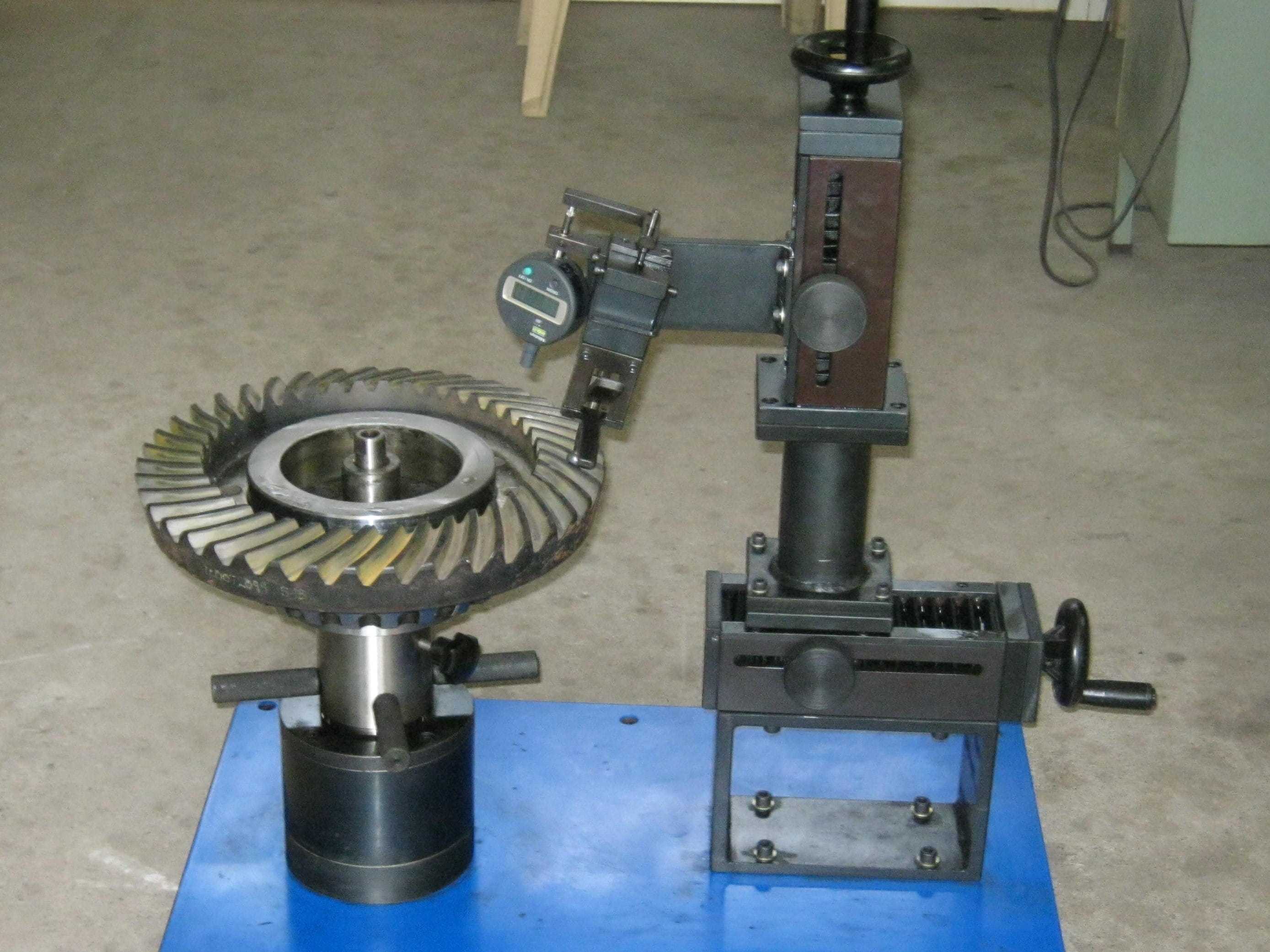
| Over-pin / over-ball check | Pin or ball measurement across teeth | Indirect check of tooth size relation | Better for inspection than rough field work |
Center distance check | Compare with mating gear and shaft spacing | Confirms working pair compatibility | Best used with both parts together |
Gear metrology | Profile, lead, pitch, runout data | High-confidence inspection result | Best for precision programs |
Practical factory note
In workshops, PCD is rarely "measured" like outside diameter because it is not a physical edge. It is normally confirmed through calculation, drawing review, reverse checking, or metrology. That is why buyers should not expect a supplier to simply put a caliper on a gear and read the pitch diameter directly. The correct question is usually: How was the PCD calculated or verified?
What correct PCD control improves
What correct PCD control improves
| Benefit | What improves | Practical result |
| Correct center distance | Mating gears sit in the right working position | Better meshing and lower fit risk |
| Better tooth compatibility | Module, pitch, and tooth size stay aligned | Less mismatch in replacement work |
| More stable ratio | Gear pair runs as designed | Better transmission consistency |
Better inspection logic | Buyers check the right parameter, not only OD | Fewer quotation and sampling mistakes |
Lower project risk | Geometry is reviewed before production | Less rework and fewer field complaints |
The main value of checking PCD correctly is not only "getting the right number." It is reducing the chance of building a part that looks correct but behaves badly. In many cases, that saves more time and money than any later correction.
Common gear PCD mistakes buyers should avoid
● Treating outside diameter as PCD
OD is easy to measure, but it is not the same as pitch diameter. This is the most common mistake in sample-based work.
● Ignoring tooth count when matching an old gear
A similar-looking gear can still give the wrong ratio or wrong center distance if the tooth count changes.
● Mixing module and DP
Metric and inch systems are often confused in international projects. That usually leads to the wrong tooth size.
● Using spur gear logic directly on helical gears
Helical gears may require transverse module review, not just normal module from a simple note.
● Checking one part without the mating part
PCD is most meaningful when the working pair is understood. Reviewing only one part can hide mismatch risk.
For replacement projects, the safest approach is to provide both the old gear and the mating part when possible. Photos of the wear area, contact marks, and the installed center distance can also speed up the review.
Why Choose PairGears
At PairGears, we do not treat gear PCD as a number to be copied blindly from a sample or guessed from one visible diameter. We review it together with tooth count, module or DP, center distance, mating part condition, and the actual working layout.
● practical review of custom and replacement gear geometry
● matching logic for Agricultural Machinery, Heavy Trucks, Construction Equipment, and EV drivetrains
● drawing-based, sample-based, and OEM-number-based projects
● inspection planning that connects PCD to real fit and meshing behavior
● repeatable manufacturing routes for working gear pairs, not only single parts
This is especially useful when buyers are dealing with worn samples, unclear old drawings, or replacement parts that must match existing shafts, housings, and mating gears.
FAQ
Q1: Is gear PCD the same as outside diameter?
No. PCD is the pitch circle diameter, a working reference circle. Outside diameter is the visible diameter across the tooth tips.
Q2: Can PCD be measured directly with a caliper?
Not in the same way as OD. PCD is usually calculated, estimated, or checked through gear data and metrology methods.
Q3: How is gear PCD calculated in a metric system?
For a standard metric gear, PCD is usually calculated as module × number of teeth.
Q4: Why is PCD important in replacement projects?
Because a gear can look similar in size but still mesh incorrectly if the pitch diameter, module, or tooth count is wrong.
Q5: What should buyers provide to help confirm PCD?
A drawing, tooth count, outside diameter, module or DP if known, mating gear data, and photos or samples if available.
Conclusion
Gear PCD is not a cosmetic number on a drawing. It is one of the basic references that controls center distance, tooth size, ratio, and meshing behavior. If it is misunderstood, the result is often a part that looks close but does not work correctly in the real assembly.
If you are preparing an RFQ, checking an old sample, or reviewing whether a replacement gear is truly compatible, you are welcome to Contact Us with your drawings, samples, mating gear data, OEM numbers, and operating conditions so PairGears can help align the PCD with a practical manufacturing and inspection plan.