
Helical Gears for Quiet, Efficient Power
1.Introduction
If a gearbox is judged by what you don't hear or feel, helical gears are often the decisive factor. Their angled teeth enter mesh gradually, spreading load across more contact and smoothing the torque ripple that turns into cabin whine, bearing heat, and premature wear.
At PairGears—a precision gear manufacturer and custom gear supplier serving agricultural machinery, heavy truck, construction equipment, and EV—we co-engineer helical gears from the first ratio sketch to final contact pattern. This article distills how to design, build, and validate helical meshes that run quiet, last long, and meet your budget and timeline.
2.What Is a Helical Gear ?
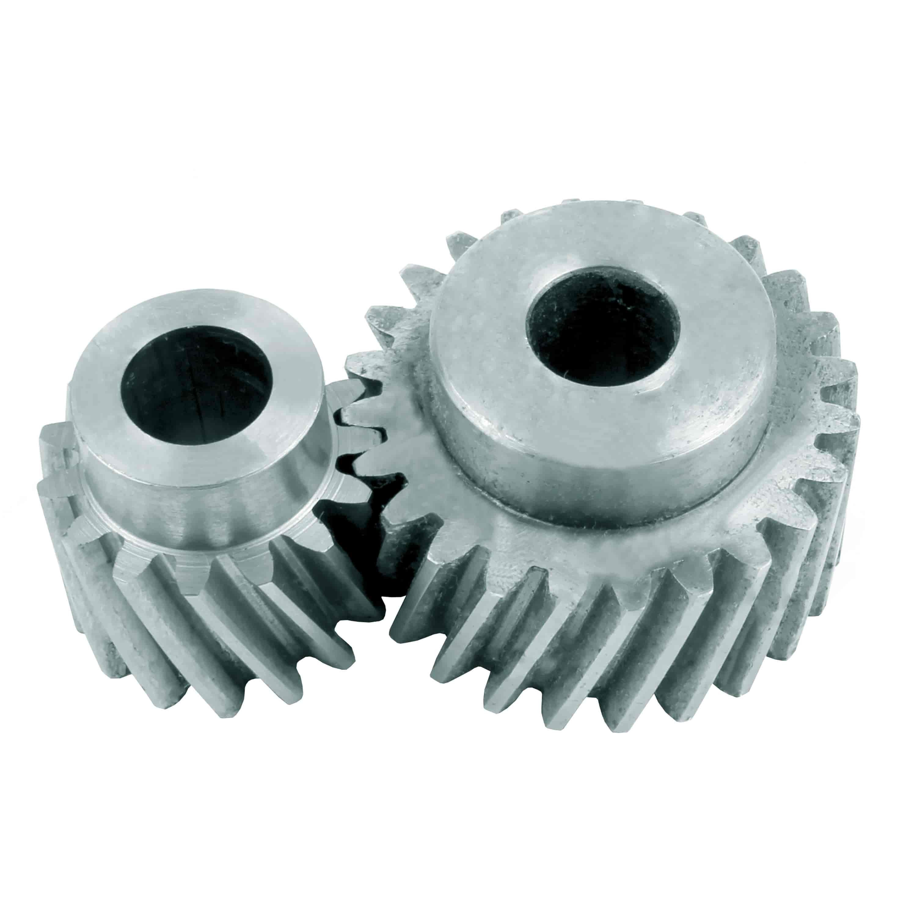
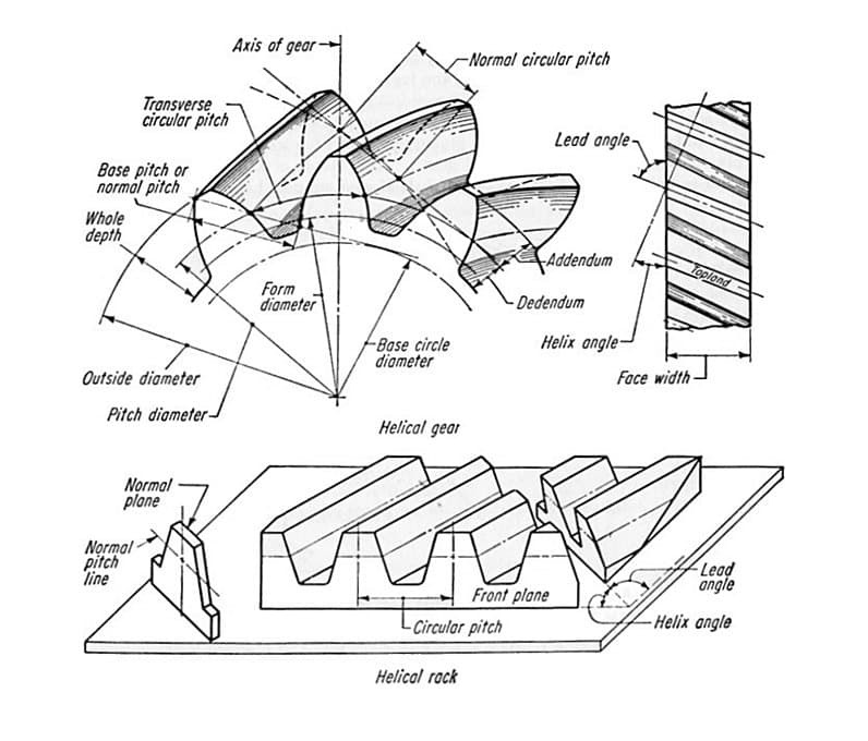
Helical gears have teeth cut along a helix angle relative to the shaft. Unlike spur gears (instant line entry), helical teeth roll in gradually, so contact grows from point → line → area. That softer entry cuts noise, vibration, and shock, improves load sharing, and supports higher speeds.
Right-hand vs left-hand: the tooth slant defines hand. For parallel shafts, use one right-hand and one left-hand gear. For crossed or right-angle shafts, you'll use matching hand depending on the layout (or move to spiral bevel/hypoid if you need a true right-angle stage with offset).
3.Core Design Parameters
| Parameter | What it controls | Practical guidance |
Module / DP | Tooth size & capacity | Size to peak torque and life; check pitting & bending safety factors. |
Pitch diameter | Ratio & mesh geometry | Locks ratio; verify center distance and bearing spans early. |
Strength vs. sensitivity | 20° is common; higher PA raises load capacity but increases bearing loads. | |
Helix angle (β) | Smoothness & thrust | 15–30° typical. Higher β = smoother + more axial thrust → size thrust bearings. |
| Face width | Load distribution | Wider face spreads load but raises misalignment sensitivity—control shaft/bearing deflection. |
| Teeth count | Ratio, contact ratio | Avoid undercut on pinions; increase overlap/contact ratio for NVH and life. |
| Backlash & micro-geometry | Noise & pattern | Set backlash window and add profile/lead crown to center the contact under load. |
Axial thrust note: Helical gears generate axial force. Balance it with a mirrored gear (opposite hand pair), thrust bearings, or a bearing stack sized for β.
4.Materials & heat treatment
Carburized alloys (20MnCr5, 18CrNiMo7-6) remain the workhorse for high torque and long life. A case of HRC 58–62 with verified effective case depth (Eht) resists pitting and scuffing while the tough core survives shocks. PairGears typically uses vacuum carburizing + gas quench to minimize distortion scatter so finishing stock is predictable.
For serviceable, cost-sensitive drives (many agricultural and construction auxiliaries), 42CrMo4/4140 in Q&T condition with selective induction hardening on flanks and journals offers robust performance with simpler processing.
Where geometry stability is king (precision modules, automation auxiliaries, some EV peripherals), nitriding (e.g., 38CrMoAlA) adds a hard diffusion layer at low temperature for very low distortion—ideal when you can't “grind it back to truth.”
On the print: specify Eht windows, surface/core hardness, retained austenite limits (for carburized sets), and finishing stock. That clarity saves weeks in PPAP.
5.Efficiency, loads, and thermal reality
Efficiency: With ground/ honed flanks and the correct oil viscosity, helical meshes routinely deliver ≥97% per stage. Poor finish or starved jets erase that gain quickly.
Axial load: The price of smoothness is thrust. Size thrust bearings and spacers accordingly; model preload growth at temperature.
Thermal drift: Center distance grows and backlash tightens at heat soak. Validate contact pattern hot and seal an oil plan (jets vs. splash) that sustains film thickness at peak speed.
6.Manufacturing that makes the drawing come true
6.1 Blank & conditioning
Start with clean forged/rolled stock; normalize or stress-relieve if the pre-form saw heavy cold work. Early datums avoid chasing runout later.
6.2 Rough machining
Turn hubs/bores, mill key features, pilot oil galleries. Balance removal to keep cores straight and residual stress low.
6.3 Tooth cutting
Hobbing is the general-purpose workhorse.
Power skiving unlocks cycle time in compact modules and internal gears with good rigidity.
Shaping covers geometries skiving can't reach.
6.4 Heat treatment
Vacuum carburize + gas quench for low scatter and uniform case.
Induction for targeted hard tracks on journals/flanks.
Nitriding when distortion must be near-zero.
6.5 Finishing
Gear grinding (profile & lead) to the specified grade;
Honing for micro-texture that accelerates run-in and lowers tonal noise;
Superfinish on bearing journals for lower friction and cooler operation.
6.6 Inspection & proof
Profile/lead/pitch charts, TIR to functional datums, flank and journal Ra/Rz, microhardness traverse & Eht, and a light contact pattern at mounting distance. For quiet programs we add spin NVH checks against target orders.
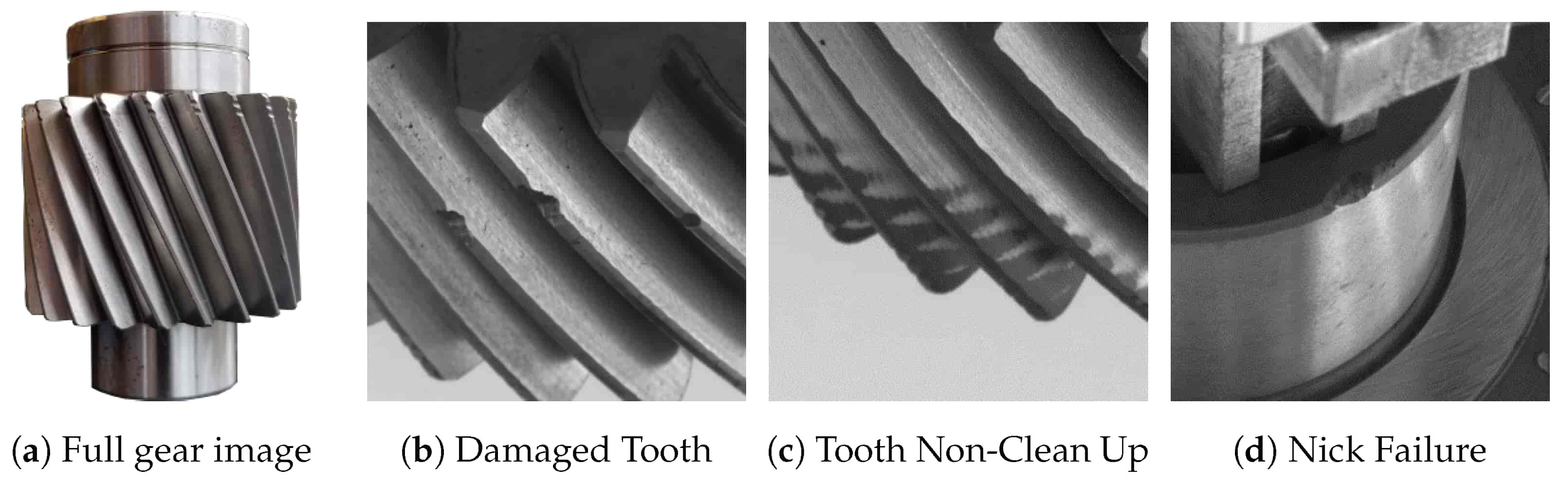
7.Typical Defects & Prevention
| Defect | Root cause | How we prevent it |
Pitting / micro-spalling | Insufficient case depth/film, misalignment | Size Eht, improve finish, crown for load, validate pattern under load. |
Scuffing | High sliding + thin oil film | Lower Ra; EP oil; adjust micro-geometry; ensure directed lubrication. |
| Edge loading | Misalignment, inadequate crown | Lead crown & profile mods; control shaft/bearing deflection. |
| Whine at fixed orders | Runout, profile/lead error | Tighten TIR to datum; grind/hone; balance rotors when needed. |
| Tooth root cracking | Stress risers, inclusions | Generous root fillet; clean steel; verify core hardness & residual stress. |
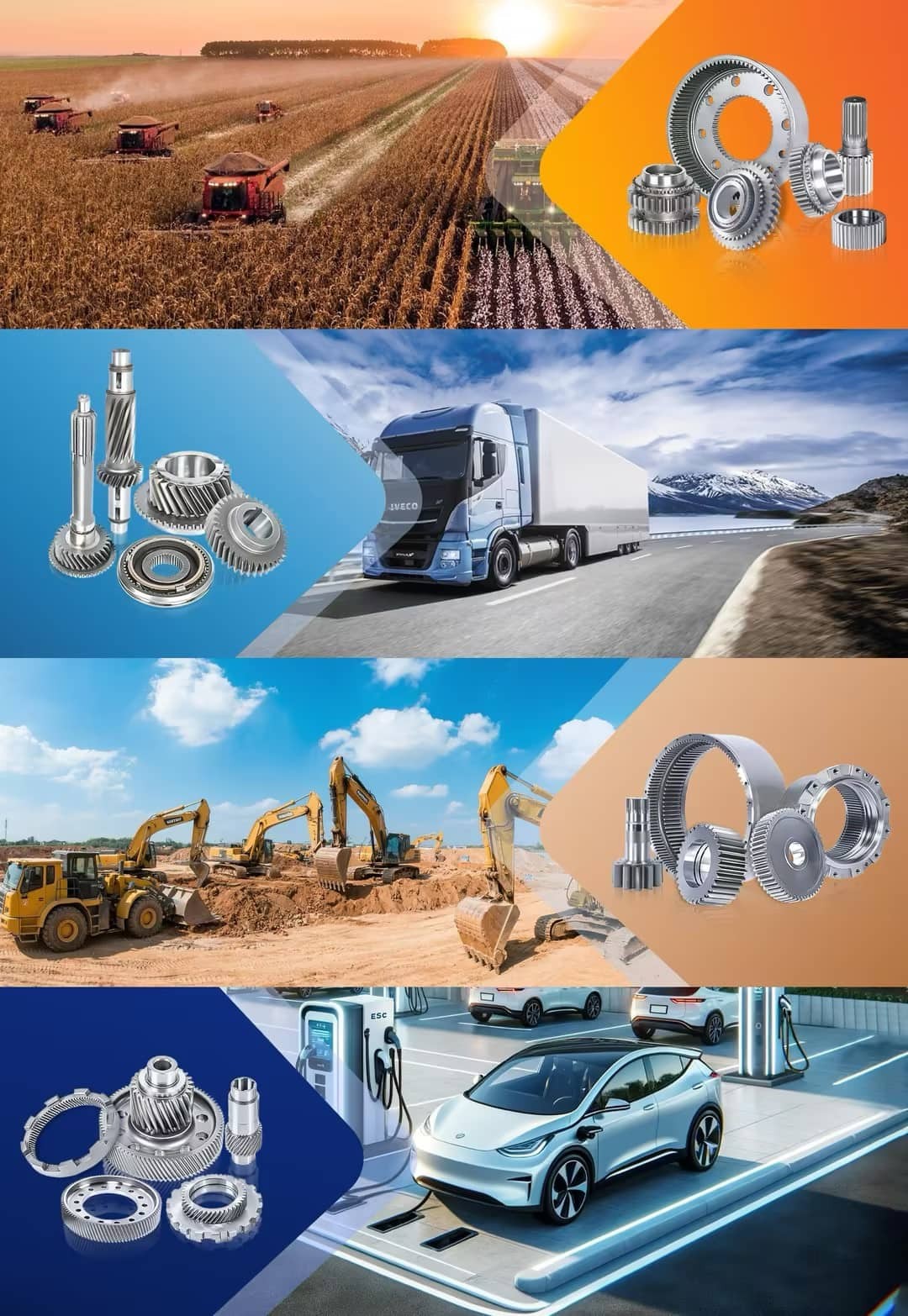
8.Applications we serve
8.1 Agricultural Machinery
Use cases: PTO gearboxes, seeders, choppers, augers.
What matters: Dirt, water, shock. Prefer Q&T + induction or carburized & ground with generous fillets and robust seals. Specify backlash that tolerates contamination without wiping films, and choose oils that keep viscosity in wide ambient swings.
8.2 Heavy Truck
Use cases: Manual/AMT transmissions, auxiliaries (PTOs, pumps).
What matters: Million-mile life and pass-by noise. Use vacuum carburizing, hard grind + hone, superfinished journals, and tight runout and micro-geometry control. Validate pattern at cold and hot center distances; plan traceability for every lot.
Use cases: Winches, slew drives, mixers, compact reducers.
What matters: Intermittent peaks and thermal rise. A tough Q&T core with deep induction or carburized case resists excursions. Use wider faces with crown, increased ribbing in housings, and oil jets that reach the mesh at odd duty cycles.
Use cases: E-axle stages and auxiliaries.
What matters: High RPM and extremely low noise floors. Demand low-scatter heat treat, honed flanks, strict TIR to functional datums, and (where applicable) ISO G-class rotor balance. Validate acoustic orders over the whole speed band and at hot oil.
9.Practical specification
Use these as starting targets—we'll tune them to your ratio, torque, bearings, and oil.
Pressure angle: 20° (consider 22.5–25° where capacity is tight; re-check bearing loads).
Helix angle β: 15–30° (NVH vs. thrust trade).
Face width: size for load; add lead crown proportional to measured deflection.
Backlash: windowed for cold/hot; reference ISO/DIN gear grade to avoid ambiguity.
Runout (to functional datum): ≤ 0.01–0.02 mm typical.
Flank finish: Ra 0.4–0.8 μm (lower for strict NVH).
Case depth (Eht): duty-matched (e.g., 0.8–1.2 mm for high-load modules).
QA artifacts: profile/lead/pitch charts, hardness traverse & Eht, TIR, contact pattern at mounting distance, journal finish, and—if relevant—spin NVH.
10.What PairGears delivers with your parts
We align our documentation with your release process:
Geometry & finish: profile/lead/pitch charts, TIR plots, flank and journal Ra/Rz.
Metallurgy: surface hardness, Eht, microhardness traverse; retained austenite (if carburized).
Function: contact-pattern images at mounting distance; spin NVH (if specified).
Traceability: material heats, furnace loads, cutter IDs, gage R&R references.
11.Conclusion
Helical gears succeed when geometry, metallurgy, finishing, bearings, lubrication, and QA are treated as one system. Do that, and you get meshes that are quiet at speed, efficient under load, and predictable in production. PairGears brings that system view—from ratio trade-offs and micro-geometry targets to vacuum carburizing recipes and hone parameters—so your program hits its NVH and durability goals with margin.
If you have a drawing (or just a duty cycle and envelope), send it over. We'll propose a right-sized stack and a practical validation plan you can launch. Contact us.

