
Input Shaft Done Right: Design, Materials, and Manufacturing
1.Introduction
At PairGears, we engineer precision power-transmission components for agricultural machinery, heavy truck, construction equipment, and EV. As a precision gear manufacturer and custom gear supplier, we build not only gears but the shafts that align and drive them—especially the input shaft, the point where engine or motor torque first enters the gearbox.
This guide distills what we've learned about input shafts: how to specify the geometry, materials, heat treatment, surface finish, balance, lubrication paths, and tolerances that keep drivetrains quiet and durable.
2.What an input shaft actually does
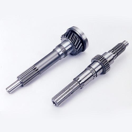
The input shaft couples the prime mover (ICE, e-motor, PTO, hydraulic motor) to the gearbox. Its jobs are deceptively simple:
1. Transmit torque & speed into the first gearset or synchronizer.
2. Set datums for coaxial alignment (bearing seats, spline datums, pilot diameters).
3. Route lubrication (oil holes, helical grooves) to bearings and gear meshes.
4. Control NVH via runout, balance, surface finish, and micro-geometry at splines and journals.
Because it sits at the front of the transmission, any eccentricity, chatter, or surface defect here is amplified downstream—so the input shaft is a precision part, not"just a bar with splines".
3.Load cases and design drivers
Torsion: steady + transient torque (start-up, gear changes, shock).
Bending: from gear mesh forces, belt/chain loads, or clutch release loads.
Axial thrust: from helical gears or clutch actuation.
Dynamics: critical speed margin, torsional natural frequencies, and balance.
Thermal growth & fits: bearing preload/clearance changes with temperature.
Rule of thumb: freeze the bearing arrangement and clutch/gear interface early, then back-solve shaft diameters and fillets for fatigue life and deflection limits.
4.Materials & heat-treat stacks (what actually works)
| Duty / Sector | Typical Material | Heat Treat | Why it’s chosen |
Heavy truck, high torque | 4140, 18CrNiMo7-6 | journals or carburize + grind | surfaces; deep case for spline wear |
Agriculture, mixed shock | 40Cr / 5140, 20CrMnTi | Q&T + local induction or carburize where splines see dirt | Impact tolerance, serviceability |
| Construction, large modules | 42CrMo / 4340 | Q&T; induction selective | Robust, repairable, good tooth-seat hardness |
| EV, high speed & NVH | 16MnCr5 / 20MnCr5 | Low-pressure carburize + gas quench + hard grind/superfinish | Low distortion, quiet running, long bearing life |
Tips:
Carburize for long spline life and contact strength (EV & truck).
Induction when you want selective hardening and simpler finishing (ag & construction).
Nitriding if distortion budgets are tight (precision automation).
Specify effective case depth (Eht), surface hardness, and core hardness on the print; leave grind stock accordingly.
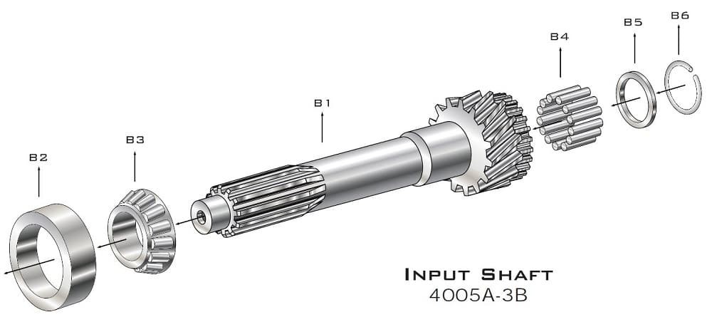
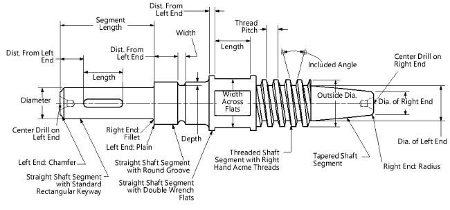
5.Geometry that saves programs
Fillets: generous under-cut fillets at spline shoulders and gear seats cut peak stress—specify controlled radii and matching reliefs in mating parts.
Chamfers & lead-ins: at splines and press fits to prevent galling during assembly.
Spline class & fit: choose involute spline class to balance torque capacity, backlash, and NVH; specify runout relative to datum A (primary journal).
Bearing seats: hardness + roundness + waviness control; specify surface finish (e.g., Ra ≤ 0.2–0.4 μm) and profile tolerance to keep preload stable.
Oil logistics: axial cross-drills, annular grooves, and metering orifices—design for flow, not just presence.
Balance features: shallow drill plugs or flats placed away from stress hot-spots; keep residual unbalance below the rotor spec (ISO G grades or OEM target).
6.Manufacturing flow we trust
Blanking & pre-machining
Forged/rolled bar → stress-relief or normalizing if cold-worked. Turn datums and reference centers.
Rough machining
Turn shoulders/diameters; mill key features; pilot-drill oilways; pre-cut spline stock. Maintain consistent residual stress.
Carburize/quench/temper or Q&T + induction or nitriding per stack.
Use coupons each furnace load; verify surface hardness and Eht.
Finish machining / grinding
OD grind bearing seats and journals.
Form grind gear seats if integral gear.
Spline: hobbing/shaping + roll/brush deburr; grind or shave to class if required.
Superfinish critical journals (EV/high speed).
Deburr & clean
Thermal or brush deburr, ultrasonic clean; verify oilways are clear.
Balance & verification
Single or two-plane balance; mark correction; document residual unbalance.
Final QA
Profile/lead at splines, runout to primary datum, surface roughness, hardness map, contact pattern (if assembled), and leak/flow test for lubrication drillings.
7.Tolerances that keep NVH down
Total indicated runout (TIR) of primary journal to spline datum: ≤ 0.01–0.02 mm (application-dependent).
Roundness / waviness on bearing seats: ≤ 0.003–0.005 mm; Ra ≤ 0.2–0.4 μm.
Spline parallelism/concentricity to datum A: ≤ 0.02 mm.
Oilway burrs: none permitted; 100% borescope or airflow check on critical lines.
Residual unbalance: meet system rotor spec (e.g., ≤ ISO G2.5 for high-speed EV inputs).
8.Surface finishing & coatings
Superfinishing (stone or vibratory) on journals reduces bearing temperature and noise.
Phosphate or thin-film coatings on splines (when corrosion or fretting is a risk).
Shot peening at fillets boosts bending fatigue (verify Almen intensity).
Dry-film lubricants (selectively) for press fits or sliding assembly.
9.Failure modes & how to avoid them
| Failure | Likely Root Cause | Prevention |
Spline wear/fretting | Low case depth, poor hardness, misalignment, dry interface | Deeper case; tighter runout; anti-fretting coating; ensure lube path |
Bearing blueing | Rough journal, imbalance, poor oil feed | Superfinish; balance; verify oilway flow |
| Torsional fatigue | Sharp fillets, inclusions, under-spec core hardness | Generous fillets; clean steel; confirm core hardness |
| Scuffing/galling (assembly) | No chamfer/lead-in, tight interference, poor lube | Add lead-ins; controlled fits; assembly lube |
| Gear whine at input speeds | Runout, spline error, poor micro-geometry | Tighten TIR; high-class spline; check datum strategy |
10.Validation & QA artifacts PairGears delivers
Geometry: runout/concentricity to datum, bearing seat charts, spline inspection (profile/lead/pitch).
Metallurgy: surface hardness, Eht (if case-hardened), microhardness traverse, retained austenite (as required).
Surface state: roughness (Ra/Rz), superfinish records, peening certifications.
Function: oilway airflow/leak test, balance report, contact-pattern (if shaft shipped with mating gear).
Traceability: material heat, furnace load logs, tool IDs, gage R&R references.
11.Sector notes
11.1 Agricultural machinery
Mud and shock loads punish splines and seals. Use deep case on splines, robust seals, generous fillets, and sized oilways. Q&T + induction is a good cost/performance choice on large modules; superfinish critical journals.
11.2 Heavy truck
Million-mile expectations with strict pass-by NVH. Favor vacuum carburizing + gas quench for low distortion scatter, hard grind/superfinish, and tight runout. Balance and micro-geometry control pay back in warranty.
Transient overloads dominate. Q&T for a tough core, selective induction on bearing tracks and splines, shot peening at fillets. Keep oilways big enough for hot, dirty oil.
11.4 EV
High rpm and silence. Low-distortion carburize with narrow scatter, superfinished journals, ISO G2.5 or better balance, tight TIR, and validated micro-geometry. Re-confirm critical speeds after design changes.
12.A practical checklist you can copy to your drawing review
1.Freeze bearing type/spans and clutch/gear/spline interfaces.
2.Select material + heat-treat for duty (Eht, hardness windows, grind stock).
3.Lock fillets/reliefs, spline class & datums, chamfers/lead-ins.
4.Design oilways for flow; define deburr and verification method.
5.Define journal finishes and waviness, not just Ra.
6.Allocate balance method and residual spec early.
7.Specify QA artifacts (tooth-form/spline charts, hardness map, airflow, balance, runout) on the print or control plan.
13.Conclusion
A well-engineered input shaft reduces whine, cools bearings, stabilizes contact patterns, and stretches service life—across tractors, long-haul trucks, cranes, and EV e-axles. Treat it like a precision component: choose the right metallurgy, design the geometry that fights stress and misalignment, control surface and balance, and verify with artifacts that prove it.
Have a drawing or target spec? Let's review it together,Contact us.

