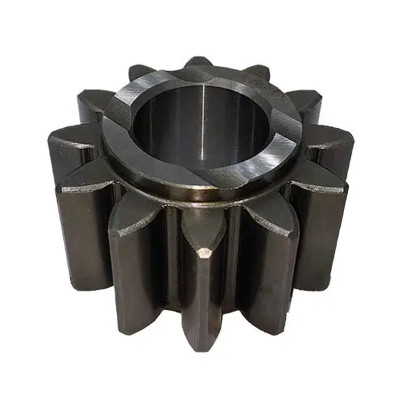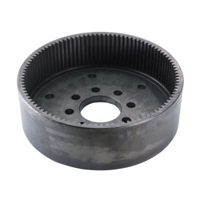
Involute Gears: Tooth Profile, Meshing and Inspection
Introduction
Involute gears are used in many transmission systems because their tooth shape is practical, stable, and easier to manufacture consistently than many special profiles. The curve on the tooth flank may look like a small detail, but it directly affects how two gears contact each other, how smoothly torque is transferred, and how sensitive the gear pair is to small assembly variation.
At PairGears, we manufacture custom precision gears and gear sets for Agricultural Machinery, Heavy-Duty Trucks, Construction Equipment, and EV drivetrains. In real projects, the main question is not whether a gear is "involute" in theory. The real question is whether the tooth profile, mating condition, heat treatment, and inspection level are all right for the application. This guide explains involute gears from a practical factory and buyer perspective, with a focus on tooth profile, meshing behavior, and inspection points that matter before production or replacement.
What are involute gears?
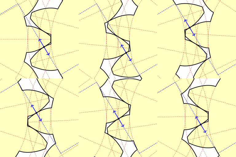
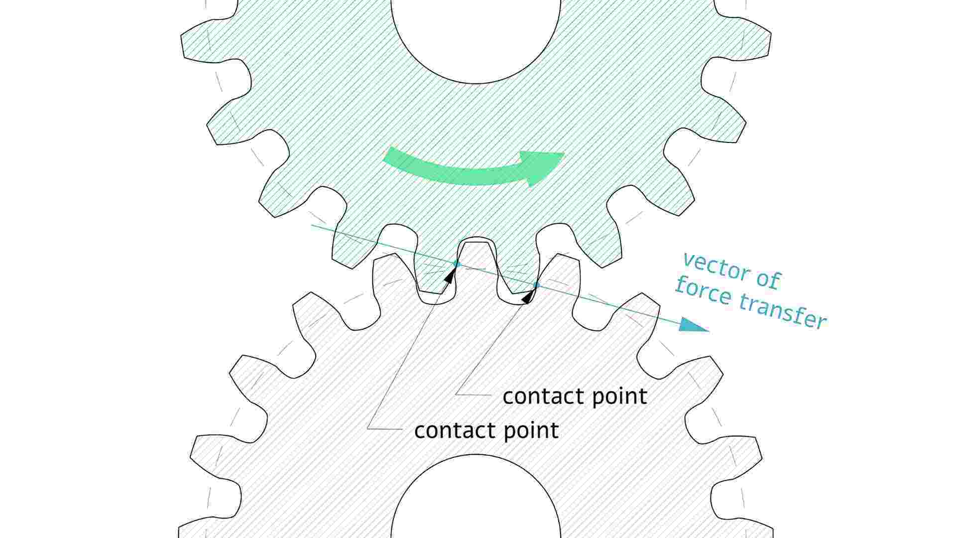
Involute gears are gears whose tooth flanks are generated from an involute curve so they can transmit motion with a stable velocity ratio.
Why the involute tooth profile matters
Why tooth profile accuracy matters
In many projects, the problem is not only tooth count or gear size. Two gears can have the right ratio on paper, but if the involute tooth form is wrong, the system can still run rough, noisy, or wear too quickly.
Why involute gears are widely used
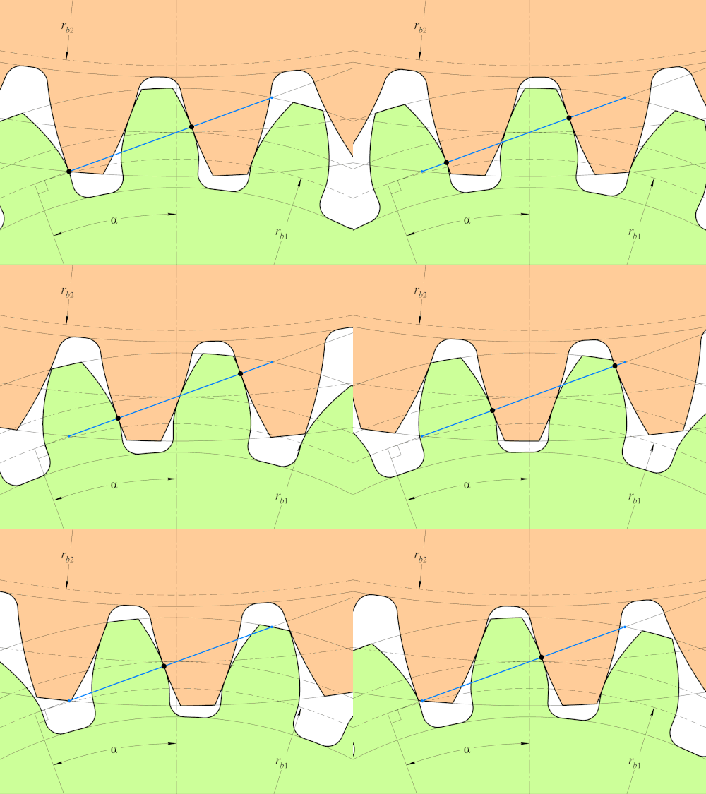
Involute gears are widely used because the tooth profile helps keep a stable transmission relationship even when center distance is not perfectly ideal. Real assemblies always include some tolerance, so this practical forgiveness is one reason involute gears remain the standard choice in many transmission systems.
Why meshing and inspection should be reviewed together
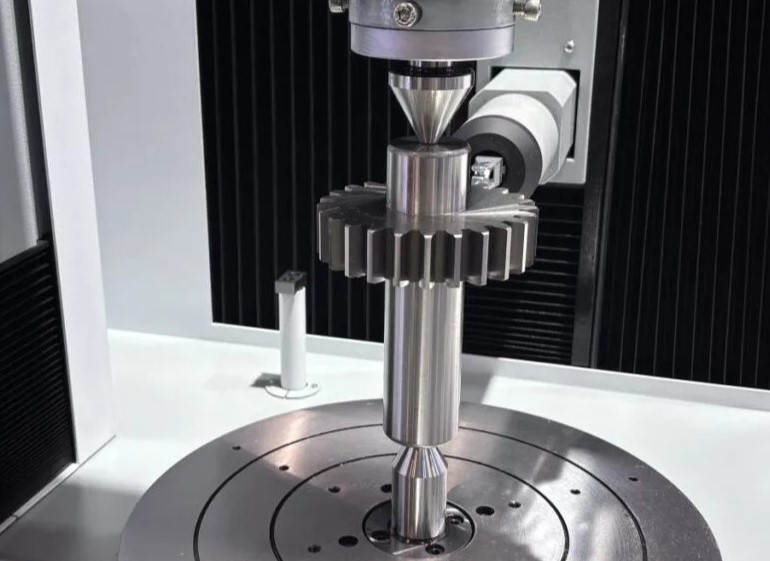
Involute performance depends on more than the drawing. The tooth form has to be generated correctly during cutting, stay stable through heat treatment, and then be checked by the right inspection methods. In real factory work, many problems come from the link between these steps, not from the CAD model alone.
Main involute gear types used in practice
| Type | Tooth / layout feature | Common use | Key inspection focus |
| Spur involute gear | Straight teeth, parallel shafts | Simple drives, reducers, machinery | Profile, pitch, runout, backlash |
| Helical involute gear | Angled teeth, smoother contact | Higher-load or smoother-running systems | Profile, lead, helix angle, contact pattern |
| Internal involute gear | Teeth on inner diameter | Compact gear sets, planetary arrangements | Tooth profile, concentricity, mating pinion fit |
Involute spline | Multiple teeth for shaft connection | Torque transfer between shaft and hub | Tooth thickness, fit, runout, hardness |
Rack and pinion | Linear rack with involute pinion | Linear motion and positioning | Tooth pitch, contact, straightness, wear |
For custom projects, the gear type is only the starting point. Buyers still need to confirm module or DP, pressure angle, tooth count, material, heat treatment, accuracy level, and mating part condition.
Where involute gears are commonly used
● Agricultural Machinery
Involute gears are widely used in gearboxes, transfer drives, feeder systems, and differential-related parts where repeated load and practical replacement fit matter.
● Heavy-Duty Trucks
Transmission gears, synchronizer-related components, shaft gears, and differential gears rely on stable tooth geometry, controlled backlash, and repeatable contact under high torque.
● Construction Equipment
Reducers, travel systems, and drive stages often work under shock load and contaminated conditions, so tooth profile stability and heat treatment control are critical.
● EV Drivetrains
Compact, high-speed gear stages usually require tighter geometry control, lower noise, and better repeatability, which makes involute profile quality even more important.
In all four sectors, the gear must do more than fit the housing. It must mesh correctly, carry load, and stay stable in real service.
What buyers and engineers should check first
Core geometry checks come first
A reliable involute gear depends on more than the visible tooth shape. The full gear geometry and production route must work together, especially when the gear has to match an existing mate or perform consistently across batches.
| Feature | What it means | Why it matters |
| Correct tooth profile | Tooth flank follows the required involute form | Supports smooth meshing and stable motion |
| Proper pressure angle | Commonly specified on the drawing | Affects tooth strength, contact, and bearing load |
| Accurate pitch | Tooth spacing stays consistent around the gear | Reduces periodic motion variation |
Controlled lead or helix | Tooth direction stays correct across the face width | Helps avoid edge contact |
Stable runout | Gear rotates around the correct datum | Reduces wobble and uneven mesh |
Correct tooth thickness | Tooth size supports proper backlash | Prevents tight running or excessive play |
Suitable heat treatment | Hardness and case depth match the duty cycle | Improves wear resistance and fatigue life |
Clear inspection reporting | Key geometry and hardness data can be verified | Supports repeat production and replacement confidence |
Practical factory note
A gear can pass a few basic size checks and still perform poorly if the involute profile, lead, or runout is unstable. That is why buyers should not judge involute gears only by outside diameter, tooth count, or visual appearance. The functional tooth geometry is what decides how the pair will really run.
What good involute geometry improves
| Benefit | What improves | Practical result |
| Smoother meshing | Tooth contact remains controlled | Lower noise and vibration |
| Better tolerance to small mounting variation | Center distance changes are less damaging | More practical assembly and replacement |
| More stable transmission | Velocity ratio stays more consistent | Better performance under load |
Better wear behavior | Contact stays in the intended area | Longer service life |
Easier production standardization | Involute gears are widely used and well understood | Better manufacturability and repeatability |
The point is not that involute gears solve everything automatically. The point is that when the profile is generated, heat treated, and inspected correctly, they give a good balance of performance and manufacturability.
Practical review points when sourcing involute gears
Review the working pair before the single part
● Involute gears work as a pair. Tooth count, module or DP, pressure angle, helix direction, and center distance logic should all be reviewed together before sampling or replacement approval.
● Check whether the supplier can explain profile and lead clearly.
A gear supplier should be able to discuss tooth profile, lead, pitch, runout, and backlash in practical terms, not only quote a drawing.
Heat treatment can change meshing behavior
● For many gears, distortion after heat treatment is one of the main reasons meshing changes. This should be reviewed early, especially in replacement or matched-pair projects.
● Review inspection capability before sampling.
If the project depends on stable involute geometry, the supplier should be able to measure and report the right inspection items, not just basic dimensions.
● Use replacement projects to verify full matching logic.
If the gear is being replaced from a worn sample or OEM number, check the mating part condition as well. A new gear cannot fix a worn or mismatched mate by itself.
Why Choose PairGears
At PairGears, we do not treat involute gears as generic toothed parts. We review the gear as part of a working transmission system.
● gear tooth profile and mating condition together, not only single-part dimensions
● practical support for Agricultural Machinery, Heavy-Duty Trucks, Construction Equipment, and EV drivetrains
● drawing-based, sample-based, and OEM-number-based custom gear projects
● inspection planning that connects tooth profile, runout, backlash, and heat treatment to real performance
● production routes that support repeatable geometry across batches
For many projects, this early review helps reduce avoidable rework, especially when the gear must match an existing mate, housing, shaft, or worn field component.
FAQ
Q1: What makes an involute gear different from other gear tooth forms?
Its tooth flank follows an involute curve, which helps maintain a stable velocity ratio and makes the gear pair more practical for manufacturing and meshing.
Q2: Why is involute profile accuracy important?
Because wrong profile shape can lead to rough running, noise, unstable contact, and early wear, even if the gear looks close in size.
Q3: Does involute gearing still work if center distance changes slightly?
Within a reasonable range, yes. One advantage of involute gears is that they can tolerate small center distance variation better than many other tooth forms.
Q4: What should buyers inspect on an involute gear?
Common checks include profile, pitch, lead, runout, tooth thickness, hardness, backlash, and mating fit, depending on the application.
Q5: Can PairGears make involute gears from samples or OEM numbers?
Yes. Projects can start from drawings, samples, OEM numbers, or application information, but for best matching results it helps to review the mating part as well.
Conclusion
Involute gears are widely used not because the term sounds technical, but because the tooth profile works well in real manufacturing and real transmission systems. When the tooth form, meshing condition, heat treatment, and inspection plan all match the application, the result is smoother running, more stable contact, and better service life.
If you are preparing an RFQ, checking a replacement gear, or reviewing whether a tooth profile is practical for production, you are welcome to Contact Us with your drawings, samples, OEM numbers, mating gear data, and operating conditions so PairGears can help align the involute gear design with a practical manufacturing and inspection plan.