
The Beauty of Gears -Mechanical Electric Drill Assembly
Introduction
At PairGears, we design and manufacture precision gears for agriculture, trucks, construction equipment, and EVs. The same engineering rigor applies to compact consumer-grade mechanisms: multi-stage reducers, clutches, and torque limiters must be robust, quiet, and easy to assemble.
Process Preview
| 1. All components are greased. To ensure assembly cleanliness, proceed with degreasing/cleaning. | |||
| 2. Due to limited solvents, high‑proof alcohol was used as a temporary degreasing agent. | |||
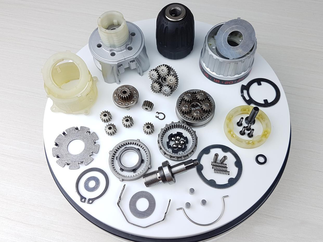
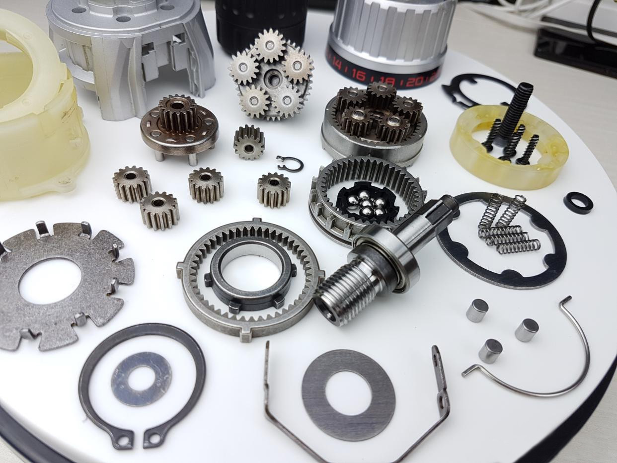
| 3. Overview after cleaning: 66 pieces in total. | |||
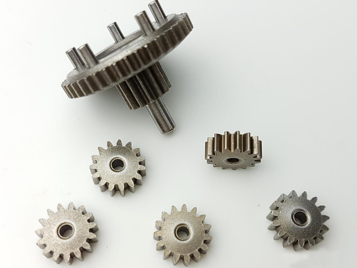
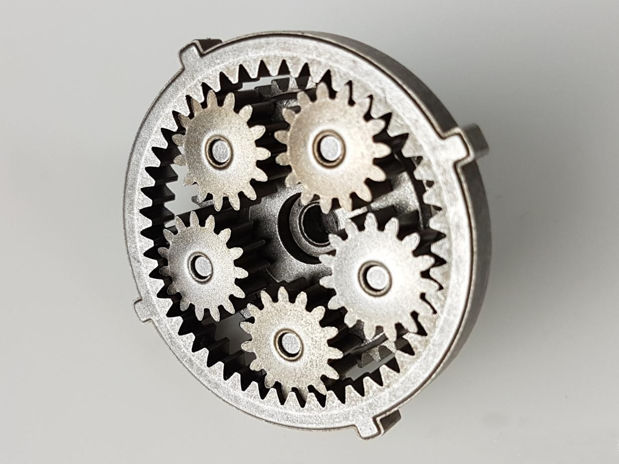
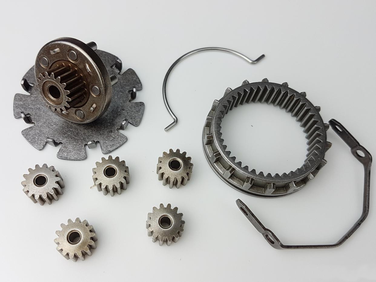
| 4. Stage I reduction: planetary assembly composed of a sun gear, ring gear, and five planet gears. | |||
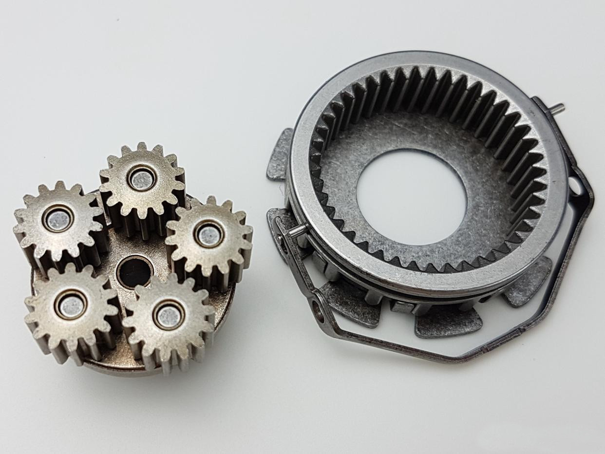
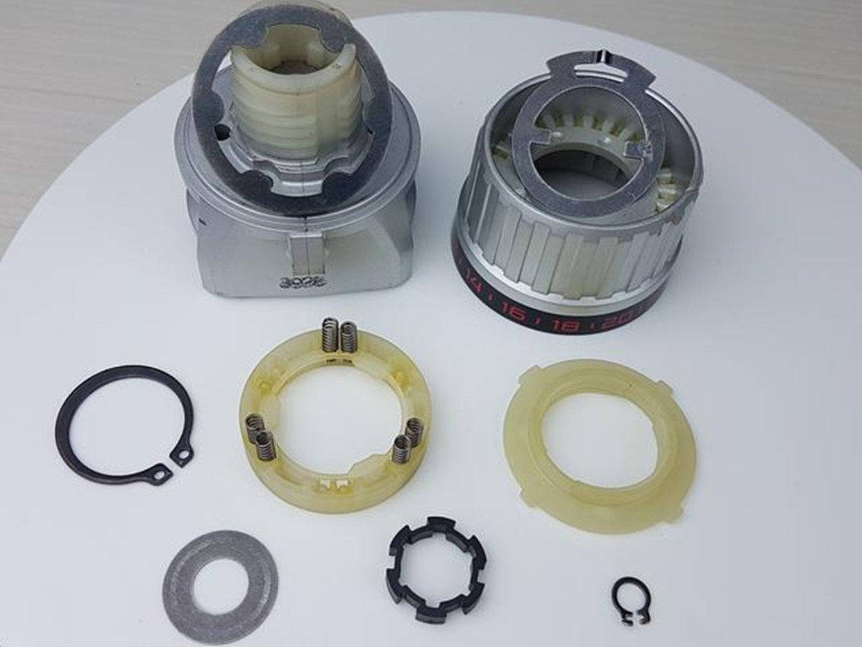
5. Stage II reduction: parts (including shifting mechanism) in pre‑assembly state. | |||
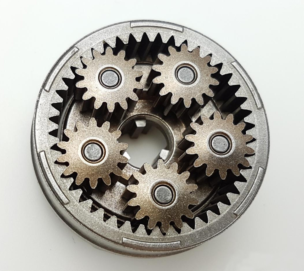
6. Combined internal assembly status of Stage I and Stage II. | |||
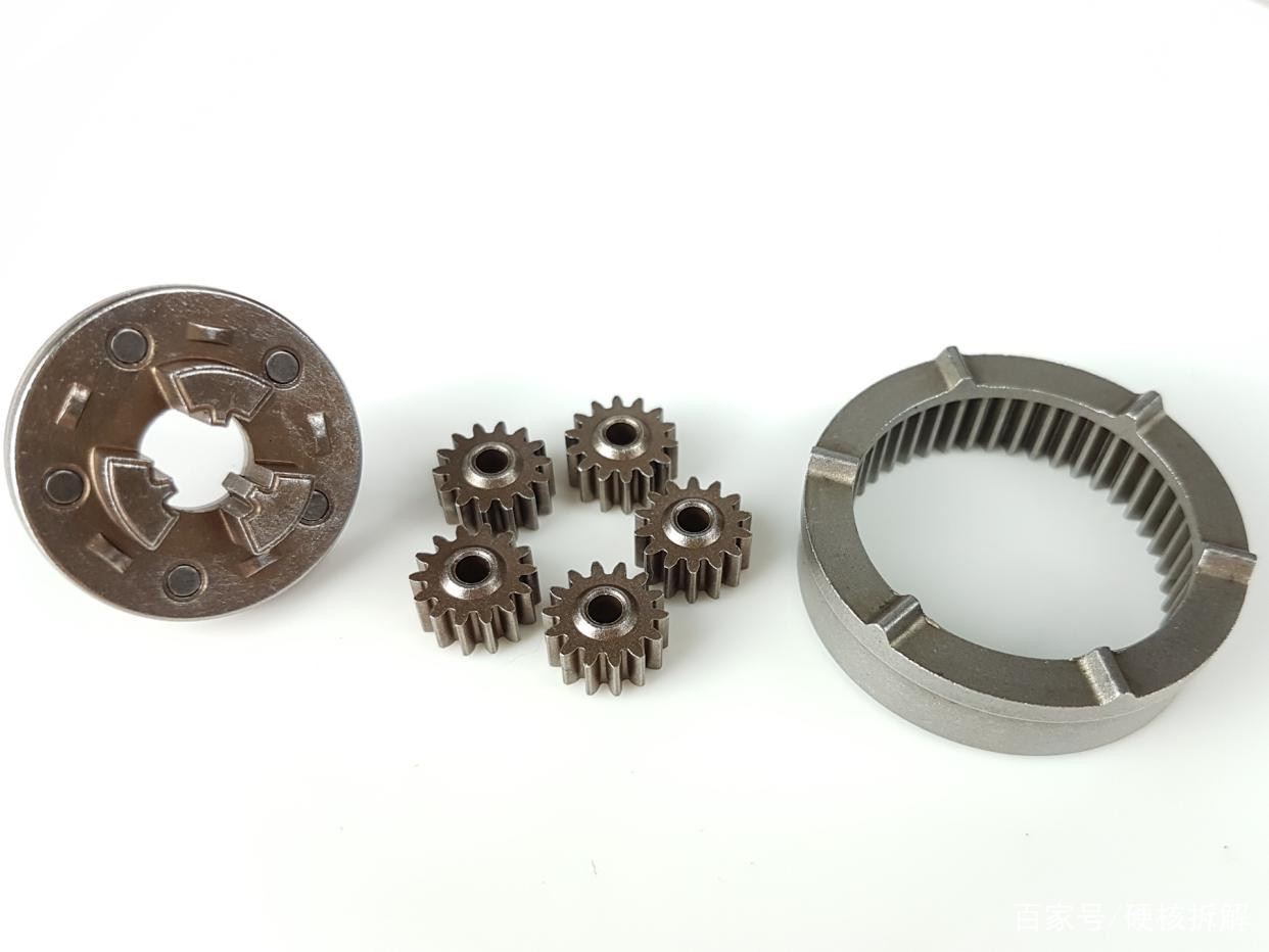
7. Stage III reduction: all parts and the completed assembly. | |||
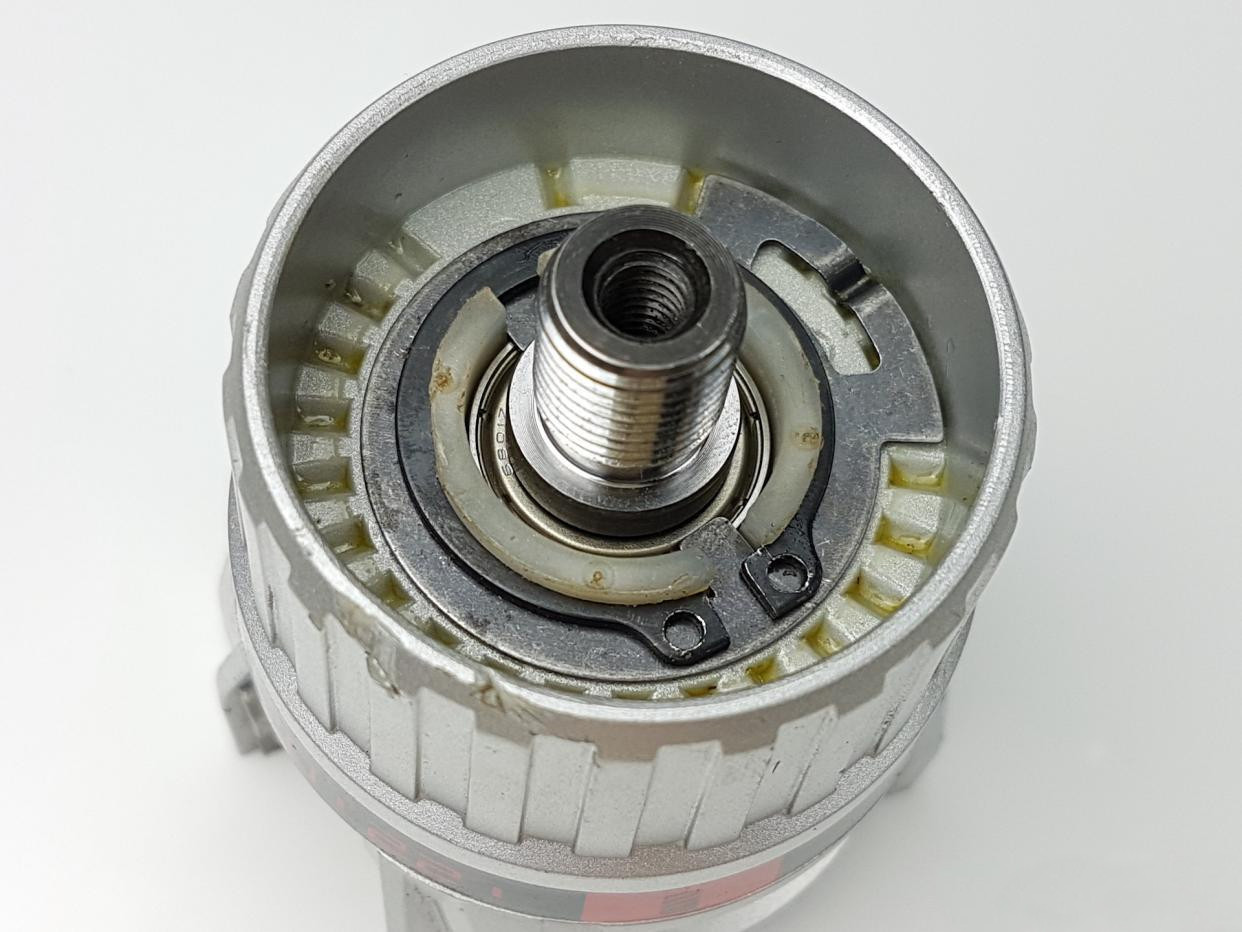
8. Appearance after cascading three planetary stages and installing the outer sleeve. | |||
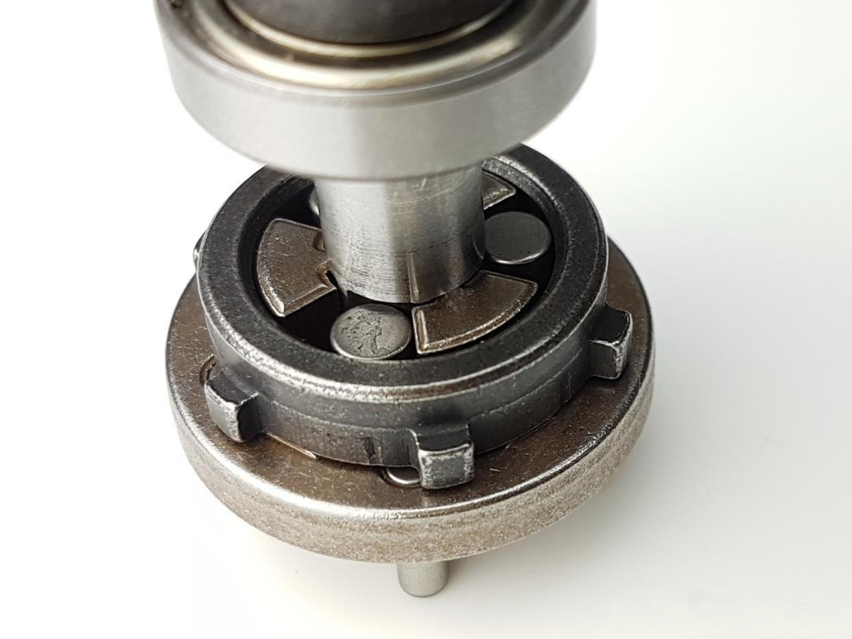
9. Mainshaft one‑way overrunning clutch: parts list and completed sub‑assembly. | |||
10. Torque adjustment (torque‑limiting clutch): when torque exceeds the set value, ball‑detent slipping occurs to unload and limit torque. | |||
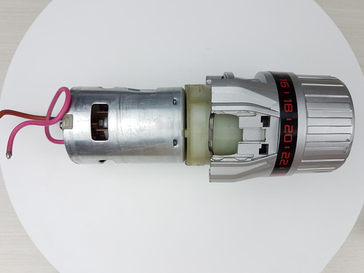
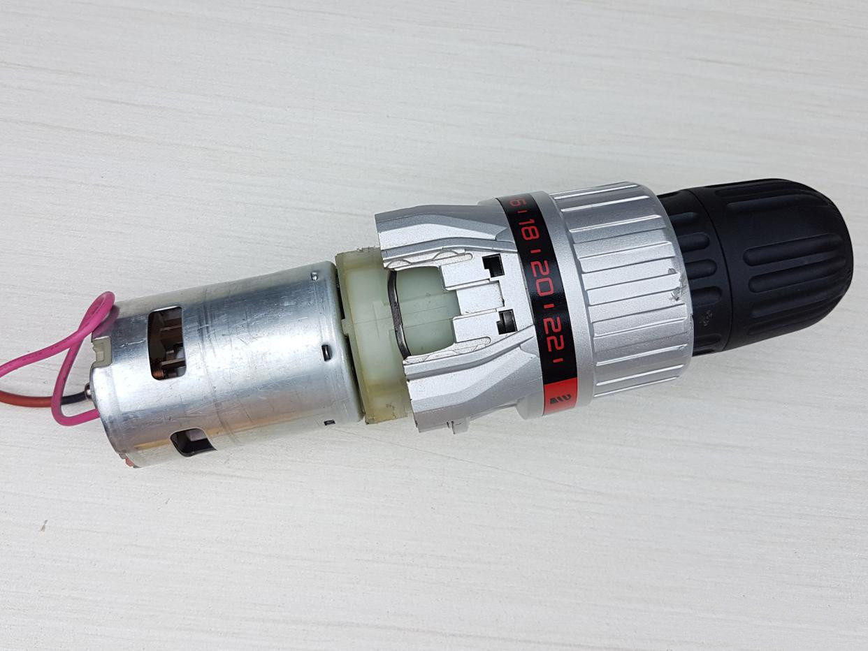
11. Assemblies completed stepwise; gearbox mates with motor; chuck installed; final assembly complete. |
Component Preparation & Cleanliness
The entire set consists of 66 parts:sun/planet/ring sets, carriers, pins and needles, thrust elements, selector parts, detent springs/balls, clutch races/rollers, spacers, seals, bearings, sleeves, and the chuck interface.
At the beginning of the disassembly, all parts and tools were neatly arranged; to prevent corrosion during storage, many parts were coated with grease. Before photographing the assembly process, Due to limited solvents, high-proof alcohol was used as a temporary degreasing agent to improve maneuverability and visibility.
On the production line, we use solvents that meet volatile organic compound (VOC) standards, ultrasonic cleaning, and controlled drying to ensure consistent adhesion of subsequent lubrication and to prevent NVH issues caused by contamination.
Cleanliness matters for NVH. Dust or fibers trapped in a tooth root or on a clutch race can propagate into noise or haptic variation. We therefore maintain a controlled assembly area, apply the specified grease weight per sub-assembly, and close the module promptly after stack-up.
PairGears tip:
Stage I: Planetary Reduction — Sun, Planets, Ring
The first reduction stage includes a sun gear (center gear), five planet gears, and an internal ring gear. This is a classic planetary (epicyclic) gear set offering high torque density and coaxial packaging. Proper backlash, lead/profile control, and ring gear concentricity are crucial for quiet operation.
We control planet pin fit and alignment, roller/needle roundness, and ring-gear concentricity. Backlash is set by the tooth geometry and confirmed during free-spin checks. Axial jewels or thrust washers are selected to establish the correct endplay target so the mesh floats under lubrication without rattle.
Manufacturing notes (PairGears):
Cut spur/helical planets via gear hobbing; apply carburizing + grind if high life/low noise is required.
Inspect profile/lead/pitch and runout to AGMA/ISO; verify sun–planet–carrier alignment before grease-packing.
Stage II: Secondary Reduction & Speed-Selection Hardware
The second reduction stage assembles as a separate submodule, including speed-selection components that alter gear ratio and output speed. Attention to carrier stiffness and selector detents reduces shift feel variation and wear.
We clock the selector parts to reference features in the carrier so that detent landings are consistent around the circumference. Materials on dog features are locally hardened for durability. We verify the detent force window at the bench before stacking the submodule onto Stage I, keeping the coaxiality by referencing ground faces and locating shoulders.
PairGears options:
Stage III: Final Reduction & Output Coupling
Set the final ratio and produce the output shaft interface for the chuck.Stack-up control. With Stage III, small errors can add up. We confirm axial endplay, spacer thickness, and bearing preload so the output runs quietly in free spin and withstands load reversals without knock. The sleeve/coupler geometry is set relative to the chuck specification to ensure consistent bit fit.
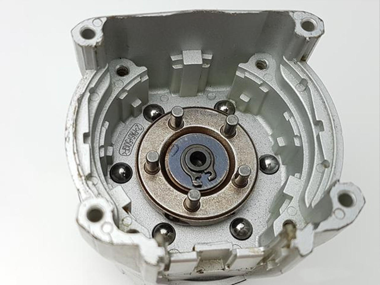
Overrunning Clutch (One-Way Clutch) on the Main Spindle
The spindle integrates a one-way clutch so that, in the forward direction, the output can free-wheel or over-run, and in the reverse direction it locks to transfer torque for controlled braking or reverse drive. Engagement smoothness depends on raceway finish, roller/needle roundness, and cage hardness; life depends on proper lubrication and heat-treat selection. We verify the locking behavior by hand-rotation tests and measure drag torque to ensure the clutch doesn’t add unnecessary loss in free-run.
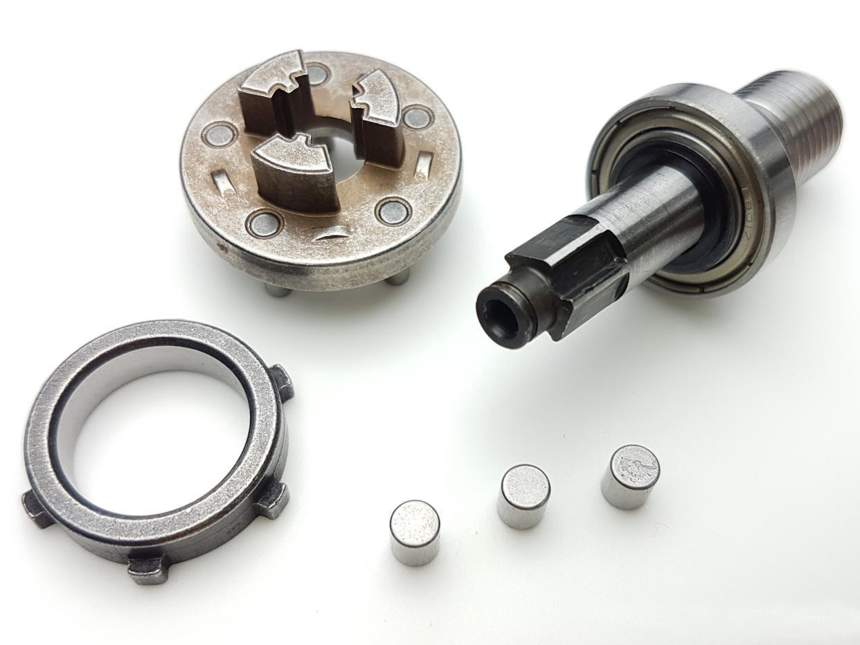
Ball-Type Torque Limiter (Adjustable Clutch)
Torque control is achieved with a ball-detent torque limiter: six steel balls seat against a ramp profile; when applied torque exceeds the set point, the balls slip, unloading the geartrain to prevent damage. Spring rate, ramp angle, and surface finish tune the release torque and the audible feedback (“click”) the user expects.
We use a ball-detent limiter as the primary overload protection. Six hardened balls sit in mating pockets. Under normal torque, the balls remain seated, transmitting load through a ramp profile. When output torque exceeds the setpoint, the balls climb the ramps and skip to the next pocket, producing the characteristic click while unloading the geartrain.
What we control: spring rate, ramp angle, pocket finish, and the stack height that defines the compression at the target torque. The release torque band is verified at the station using a calibrated fixture. We also check torque repeatability after several cycles to confirm the curve stabilizes.
PairGears engineering:
We characterize the torque curve vs. detent geometry and use post-heat-treat polishing on ramps to stabilize release torque over life.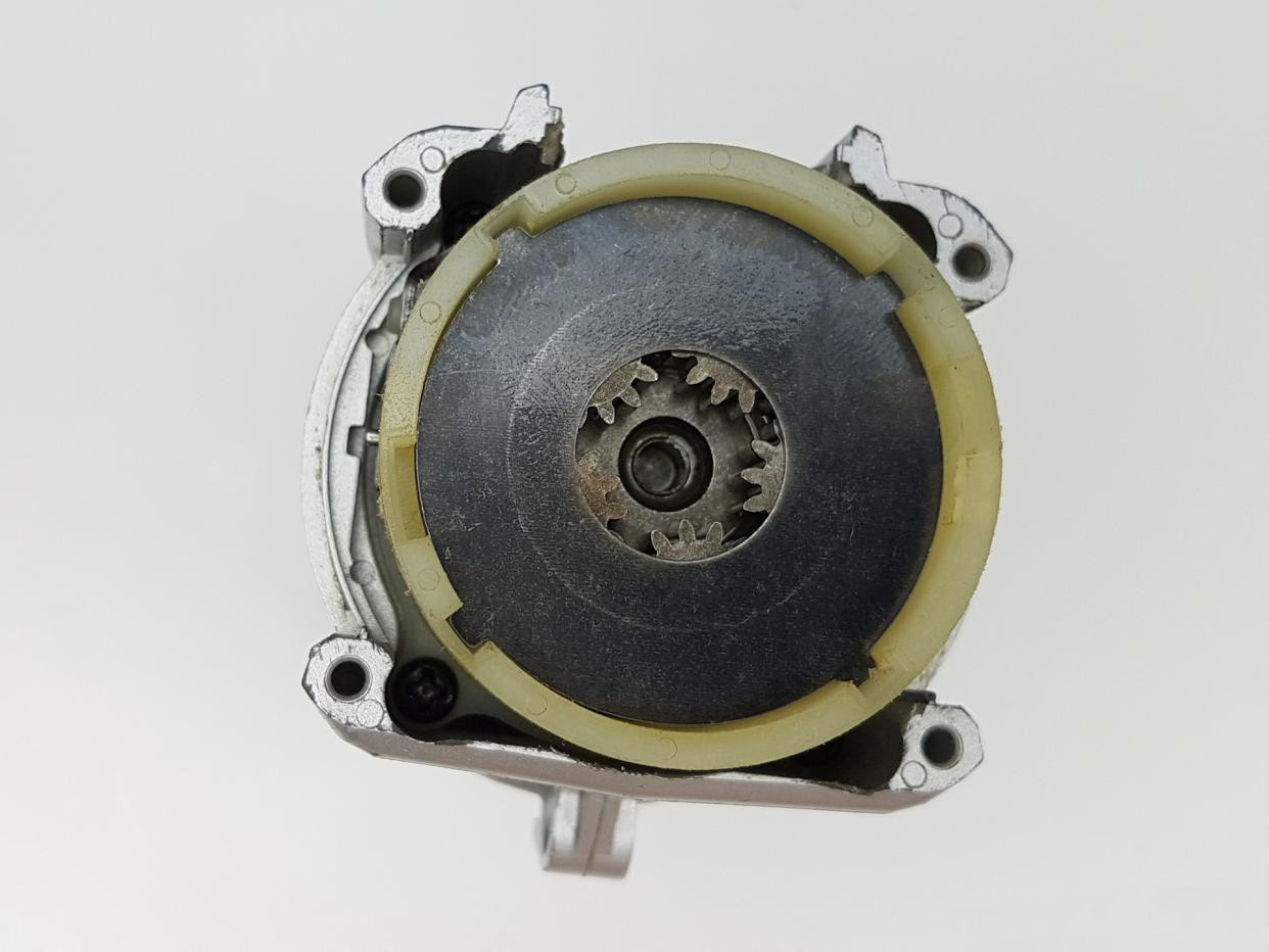
System Integration — Stacking the Three Stages
With the three planetary stages and torque limiter timed and verified, we stack the modules coaxially, install the outer sleeve (which also seals and locates), and mate the assembly to the motor interface. We then mount and secure the chuck. Before closing the unit, we confirm lubricant coverage on tooth flanks, bearing elements, and clutch raceways. The enclosure traps the lube, shields the stages from dust ingress, and fixes the relative position of selector components.
From Teardown to Production: PairGears Best Practices
Materials & Treatments: Case-hardening steels (carburized) for sun/planet/ring; nitriding for carriers where low distortion matters; induction hardening for localized wear.
Finish & NVH: Shaving or grinding for low noise; superfinishing on high-speed meshes; crowned flanks for misalignment tolerance.
QA & Traceability: Gear charts (profile/lead/pitch), runout, tooth thickness, case depth; lot-level trace and functional torque-release audits.
Assembly Aids: Color-coded subassemblies, poka-yoke fixtures for stage stacking, preset torque limiter calibration stations.
1.Drivetrain Topology & Operating Principle | |||
| Overall structure: three cascaded planetary stages + shiftable speed mechanism + one‑way overrunning clutch + ball‑detent torque limiter. | |||
| Power path: motor rotor shaft → multi‑stage internal‑mesh planetary reduction → torque limiter → overrunning clutch → chuck output. | |||
| Why three stages: high ratio and torque in a compact, coaxial layout while retaining reasonable efficiency. |
2.Torque Adjustment (Torque‑Limiting Clutch) | |||
| Construction: ball‑spring preload against detents. When threshold is exceeded, balls ride over ramps, producing cyclic slip and audible clicks. | |||
| Adjustability: rotating the torque ring varies spring preload and thus the limiting torque. | |||
Production calibration: use a torque meter to build a ‘position‑torque’ curve; typical tolerance ±10%. |
3. One‑Way Overrunning Clutch | |||
| Function: enable one‑direction torque transmission with reverse freewheeling/unloading; mitigate reverse torque spikes; improve reverse start smoothness. | |||
| Types: roller, sprag (wedge), or ball‑type—using ramps and friction‑based self‑locking engagement. |
4.Gear Materials, Heat‑Treatment & Accuracy | |||
| Common materials: carburizing steels such as 20CrMnTi, 20MnCr5, SCM415; or powder‑metallurgy gears. | |||
| Heat treatment: carburize & quench + low‑temp temper; surface hardness HRC58–62; effective case depth 0.3–0.8 mm depending on torque and life. | |||
| Accuracy & NVH: ISO grade 8–7 (or AGMA 8–10) typical; prioritize profile modifications and surface roughness for noise control. |
5. Lubrication & Sealing | |||
| Grease: lithium/calcium‑based with EP additives; typical fill is 30–50% of cavity volume. | |||
| Sealing: front oil seal/labyrinth plus housing overlaps—balancing dust/oil protection and heat dissipation. |
What This Means for Your Program
If you need a compact drive with reliable torque delivery and low noise, a triple-stage planetary with a ball-detent limiter and spindle one-way clutch is a proven recipe. We own the stack—material + heat treat + finishing + assembly tolerance—so your line gets consistent modules that pass at first power-on. Share your torque, speed, NVH, and life targets; we'll map them to module geometry, materials, and processes, then validate on our fixtures before you lock the design.
Conclusion
The electric drill we are showcasing is a small, exquisite example featuring planetary reduction, unidirectional clutch, and spherical stop torque limitation. Translating such a disassembled design into production requires control over geometry, heat treatment, surface treatment, and assembly levels.PairGears brings these disciplines together to deliver quiet, durable, and repeatable gear modules—whether for power tools or for heavy-duty drivetrains.If you're interested,Contact us.

