Gear and Gearing: Meaning, Types and Applications
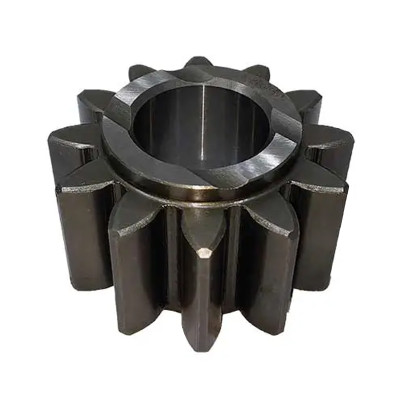
A gear is a part with teeth that transfers motion and force, while gearing describes how gears are arranged to work together. The tooth count is visible on each gear, but output speed and direction also depend on the mating gear and how the pair is fitted.
An electric motor often turns faster than the wheels it drives, so gears are placed between the motor and the wheels to lower the speed and increase the turning force, or torque. The same idea can be used in a tractor axle or a conveyor drive, although the parts may be arranged differently. PairGears is a precision gear manufacturer that makes gears and shafts to suit each assembly.
What Do Gear and Gearing Mean?
In a simple gear pair, power from a motor, an engine or another shaft reaches the driving gear first. The teeth of this gear push against the teeth of the driven gear, which then turns. This contact is known as meshing, and the smaller gear in the pair is often called the pinion. Depending on the arrangement, the pinion can either turn the larger gear or receive motion from it.
A Gear
A mechanical part with teeth that transfers motion and force to another toothed part through meshing contact.
Gearing
The way gears are arranged to work together. It can involve one pair, several pairs arranged in stages or a planetary set.
Inside the housing, the gears are held in place by the shafts and bearings, and their position affects where the teeth touch when the drive carries a load.
How Does Gearing Change Speed and Torque?
When a 20-tooth spur gear drives a 60-tooth spur gear, the larger gear makes one turn for every three turns of the smaller one. Dividing the input speed by the output speed gives a gear ratio of 3:1, so an input speed of 900 rpm gives an output speed of 300 rpm.
Direction of rotation: The two gears turn in opposite directions because their outside teeth are in direct contact.
If there were no losses, the torque at the larger gear would be three times the input torque, but friction and other losses reduce the amount available at the output. If the 60-tooth gear becomes the driver, the same pair gives a higher output speed and lower output torque.
In this example, the ratio can be found from the tooth counts, while proper gear meshing also depends on tooth shape, tooth size and the position of the gears. For standard spur gears, check the module, which indicates tooth size, and the pressure angle. The distance between shaft centers and the specified backlash, or clearance between teeth, also need checking. Two gear pairs with the same 3:1 reduction may still require different housings.
Which Gear Types Suit Different Shaft Layouts?
Parallel shafts can use spur or helical gears, while bevel gears are an option when the shaft centerlines meet. A rack and pinion can be used when the output needs to move in a straight line. The table compares common arrangements and the details buyers should check.
| Gear Type or Arrangement | Where It Fits | What to Check |
|---|---|---|
| Spur | Parallel shafts in simple drives that reduce speed, such as feeder drives. | The straight teeth do not push the gears along the shafts, but noise may be easier to hear at higher speeds. |
| Helical | Parallel shafts in transmissions and motor reducers. | The angled teeth make contact gradually, which can reduce noise, and the bearings have to take the force along the shafts. |
| Bevel | Shafts whose centerlines meet, often at 90°. | The teeth can be straight or curved, depending on the type. Both the mounting distance and the bevel gear contact pattern need to be checked. |
| Hypoid | Offset shafts, as in many truck drive axles. | The offset allows more choices for shaft position, and the lubricant needs to suit the sliding between the teeth. |
| Worm and Wheel | Shafts that are neither parallel nor intersecting, where a large reduction may be needed in one stage. | Sliding between the teeth can generate heat, so check efficiency and lubrication under the expected operating conditions. |
| Planetary | Compact drives that reduce speed and have input and output on the same centerline, such as wheel hubs. | Check which part receives power, which part delivers it and whether one part is held still. |
| Rack and Pinion | Straight-line motion in machine axes and some steering systems. | Travel length, alignment and clearance along the rack need to be checked. |
How Does a Planetary Set Work?
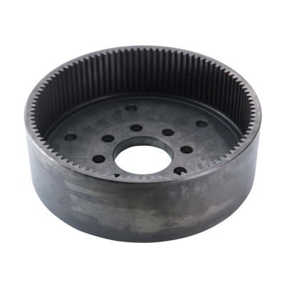
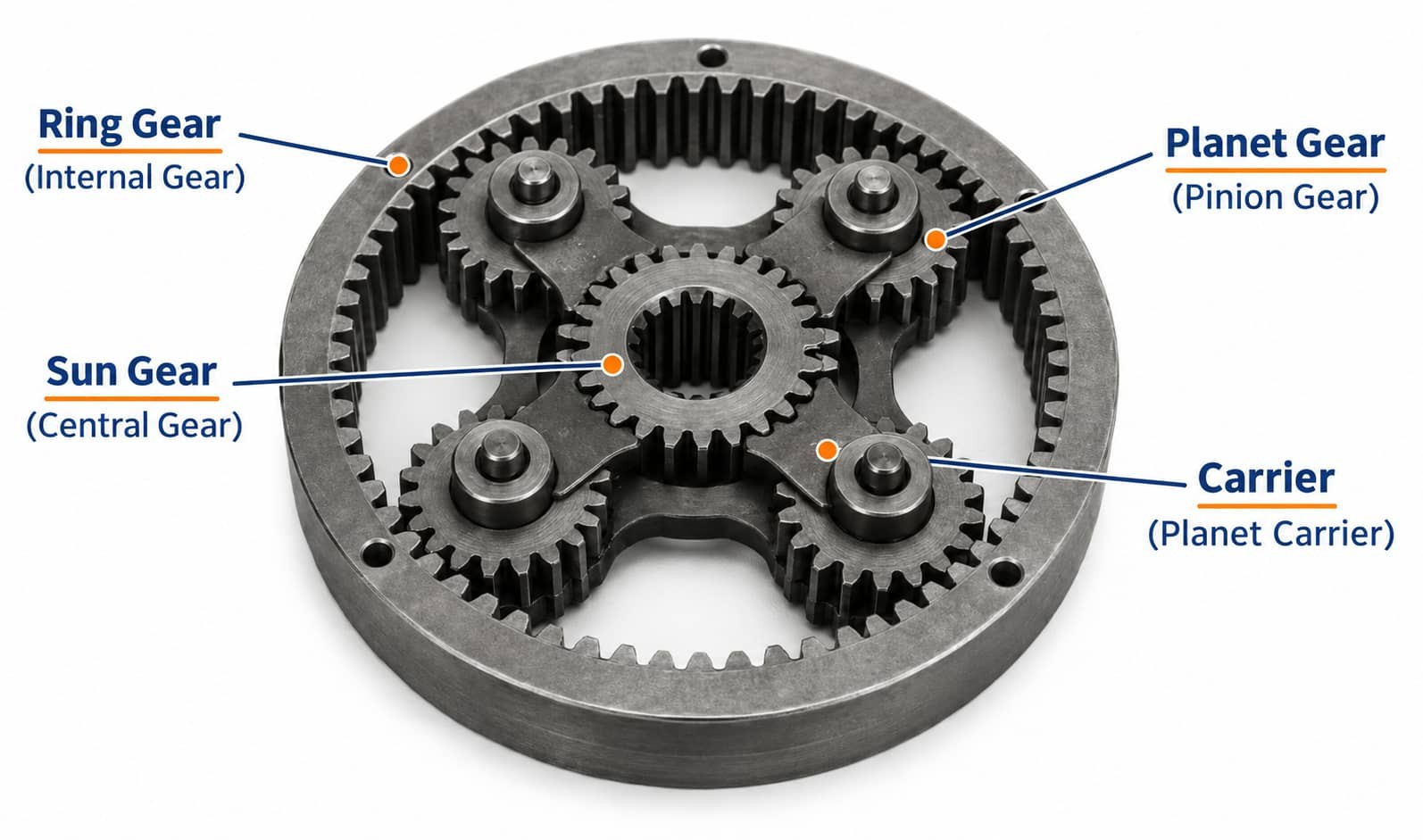
In a planetary set, the sun gear sits in the center, the planet gears are held by a carrier and the ring gear has teeth on the inside. Each planet engages with the sun and the ring, so the set shows how internal and external gears can work in the same assembly. The gear ratio depends on how the sun, ring and carrier are connected.
Where Do You Find These Gears in Service?
Gear types are selected according to shaft layout, required motion and the loads expected in the application. The examples below show what information matters when a buyer discusses a gear set for a particular machine.
Agricultural Machinery
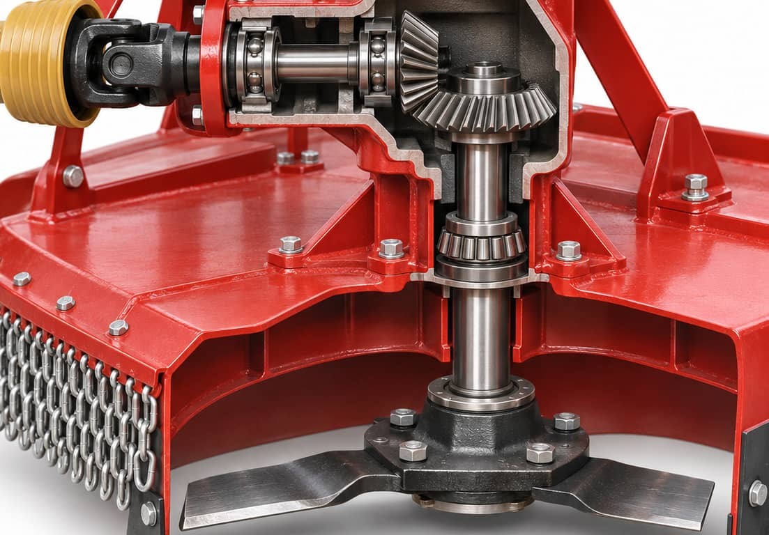
In a rotary mower, a bevel gear pair can transfer power from a horizontal input shaft to a vertical cutter shaft. The load on the drive can rise briefly when the blades pass through a thicker patch of crop, so the buyer should provide both the peak load and the normal running speed.
Recommended image: Heavy-duty truck final drive or hypoid ring-and-pinion assembly, with the pinion offset from the ring gear centerline.
Heavy-Duty Trucks
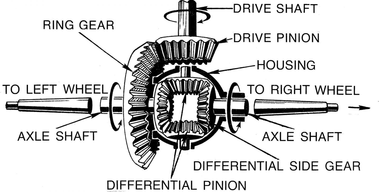
In a truck's hypoid final drive, the pinion is offset from the centerline of the ring gear, and that offset helps determine the position of the driveshaft. The gear pair lowers the speed and sends power toward the axle shafts. Because mounting depth and backlash affect where the teeth touch, the installer checks the contact pattern during assembly.
Recommended image: Wheel loader hub reduction assembly with the planetary sun gear, planet gears and ring gear visible.
Construction Equipment
A wheel loader can use a planetary set to provide the final speed reduction inside the wheel hub, where the sun, planets and ring fit around one centerline. If the machine starts and reverses often, the supplier should be told, since reversing can change the direction of the load on the teeth.
Recommended image: Electric drivetrain or e-axle gear assembly showing the motor-to-wheel reduction gears.
Electric Drivetrains
In many electric drivetrains, the gears between the motor and the wheels have a fixed ratio. Helical gears can be used in these drives because their teeth make contact gradually. Without engine noise to cover it, gear noise may be easier to hear, and even small differences in tooth accuracy, shaft alignment or housing stiffness can affect how the teeth meet under load and how the drive sounds.
What Should You Send With a Custom Gear Inquiry?
The information needed depends on how far the design has progressed. A drawing-ready project and an early-stage concept need different kinds of input.
If the Design Is Ready to Quote
Send the latest drawing and its revision number, the quantity and any material, heat treatment or inspection requirements. The mating gear drawing can also be included if available. For a bevel or hypoid pair, the mounting dimensions and the specified contact pattern help a custom gear supplier see how the two parts should fit together.
If the Design Is Still Open or From an Existing Assembly
Send a sketch of the shaft positions, together with the input speed, the required output speed and the expected torque. Explain whether the drive runs continuously, starts under load or reverses often. For a gear from an existing assembly, describe the sample condition and provide any measurements from the housing or mating part. Point out which details still need to be decided when requesting a custom gear quote.
Frequently Asked Questions
Is a Gear Train the Same as Gearing?
A gear train is a set of gears that mesh to carry motion from an input to an output, while gearing is a broader term that can also describe how the gears in a machine are arranged.
Does Adding an Idler Gear Change the Ratio?
With one idler between two external gears, the first and last gears still determine the speed ratio. The idler changes the direction of the output compared with a pair that meshes directly.
What Happens if Both Gears Have the Same Number of Teeth?
In a simple pair, two compatible gears with the same number of teeth give a 1:1 ratio. A miter gear pair is one example, with rotation transferred between intersecting shafts at the same speed.
Why Might Gears With the Same Module Fail to Mesh?
Module describes the size of the teeth, but the pressure angle, tooth shape and distance between the shafts also affect how the gears fit. If the gears are helical, the angle and direction of the slanted teeth need to be checked as well.
Can You Quote From a Sample Alone?
A sample and clear photos are enough to start a review, especially if the buyer explains where the gear runs and which part it engages with. If the teeth are worn, an original drawing or the mating gear can help the supplier check dimensions such as tooth thickness.
Conclusion
When specifying a gear set, the first details to establish are the positions of the shafts and the speed or motion needed at the output. Once these details are known, the buyer can check how the teeth will meet in the assembly and what loads the machine will apply to them.
Buyers with a drawing, a sample or a sketch can contact PairGears with a short description of how the drive will run. PairGears can review the information and identify which details need confirmation before quoting.
Planning a Custom Gear or Gearing Project?
Send PairGears your latest drawing, sample or shaft-layout sketch, together with the input speed, required output speed, expected torque and quantity. Our team can review the assembly details and identify what needs confirmation before quotation.