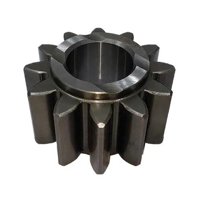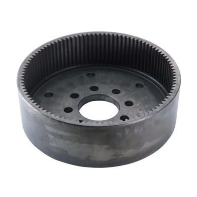
Define the datum
Identify the bore, pilot, shaft journal, face, keyway, or spline feature that actually locates the gear. The inspection report should name that reference and the drawing revision.
Measure gear concentricity and runout from the same bore, shaft journal, or locating face that controls the real assembly—not from a convenient but unrelated surface. Agree the datum scheme, fixture, indicator or measuring-center method, rotation condition, and drawing limits before production. Good tooth geometry cannot compensate for an eccentric mounting reference, because assembly runout changes the mesh in service. Identify the bore, pilot, shaft journal, face, keyway, or spline feature that actually locates the gear. The inspection report should name that reference and the drawing revision. Check radial and axial runout of the relevant mounting features separately from tooth-related measurements. Record instrument, fixture, sampling position, and any assembly condition that affects the result. If runout is high, review the blank, bore or shaft feature, fixture clamping, mounting method, and mating part. Do not assign the cause to tooth cutting without evidence. For a gear installed on a shaft, ask for the drawing revision, functional datum, runout characteristic and limit, measuring method, fixture condition, and whether the reading is taken before or after any heat treatment and finishing. PairGears’ manufacturing-process overview similarly treats datum control and runout as process-chain controls. PairGears can review a defined measurement request, but final acceptance must use the agreed drawing, datum scheme, and inspection criteria.Verify gear concentricity and runout from the functional datum
Build the check around assembly reality
Define the datum
Separate the measurements
Review the system
Example: mounted-gear inspection request
Related questions