
What do the 0–60 rows in an involute function table mean?
What do the 0–60 rows in an involute function table mean?
In an involute function table whose columns show degrees and whose side rows are marked with a prime symbol, the 0–60 rows represent angular minutes. One degree contains 60 minutes. Combine the degree column with the minute row to find the angle, then read its involute value. Always check the table headings: the row numbers are not tooth counts or decimal fractions of a degree.
Read the degree and minute headings together
The degree sign is ° and the angular-minute sign is ′. In the common degree-column/minute-row layout, column 20 and row 30 mean 20°30′ = 20 + 30/60 = 20.5°. They do not mean 20.30°. A row labelled 60 reaches the next whole degree: 20°60′ = 21°00′.
Check whether the table includes separate difference columns for interpolation. Those entries are not another angle or another involute value. Follow the particular table's rounding and interpolation instructions.
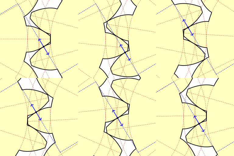
Check the lookup with the involute formula
The involute function is inv α = tan α − α, with α expressed in radians in this formula. For 20°, use α = 20π/180; the result is approximately 0.0149044. For 20°30′, use α = 20.5π/180; the result is approximately 0.0160922.
Use radians consistently in software. With a calculator in degree mode, take tan of the degree angle but subtract its radian conversion, not the degree number. The involute value is dimensionless; it is not a distance in millimeters.
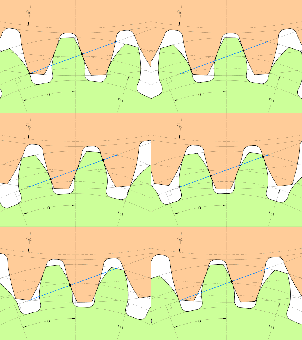
Use the angle required by the calculation
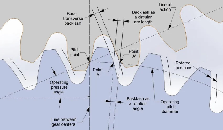
A gear calculation may call for the reference pressure angle or an operating pressure angle. Helical-gear calculations can also distinguish normal and transverse planes. Identify the required angle before entering the table; do not substitute a familiar 20° value automatically.
The PairGears involute-gear guide connects tooth geometry with meshing and inspection. A correct table lookup supports the calculation but does not verify the complete gear pair or its manufacturing accuracy.
Are you looking for a reliable manufacturer of down home textile products?
We can quickly provide customers with market analysis, technical support and customized services.- *Name
- Phone
- *Title
- *Content