
How should span measurement tolerances be set across k gear teeth?
Gear span measurement tolerance: define the method before the limit
Set a span-measurement tolerance only after the gear type, module or DP, tooth count, pressure angle, helix data, selected number of teeth, measurement plane and backlash target are defined. The drawing should state the method, reference condition and acceptance limit, so one inspection result can be compared meaningfully with another. PairGears treats span measurement as a controlled method, not a stand-alone number.
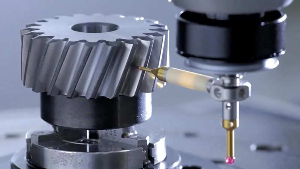
What the drawing must identify
Start with the measurement definition: name the span or base-tangent method, the exact number of teeth (k), the gear reference plane and the instrument or agreed equivalent. Then relate the limit to the specified tooth system, tooth thickness or backlash requirement, mating-gear condition and any applicable accuracy grade. For helical gears, also state whether the relevant data are normal or transverse and how the measuring plane is established.
Do not copy a span value from a worn sample without context. Wear, profile shift, tooth modification and a different measurement method can change the observed value. The PairGears tooth-thickness guide distinguishes span measurement from chordal and over-pins methods; they are related but not interchangeable.
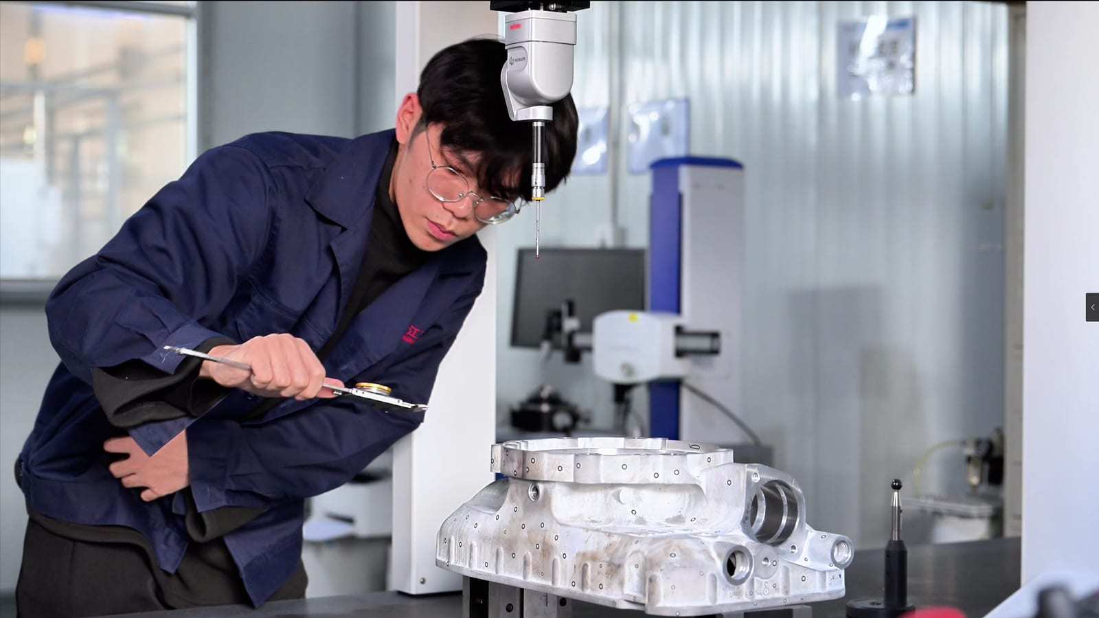
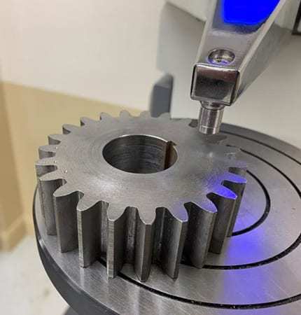
Example and decision check
For a replacement external gear, a drawing might call out “span over k teeth, measured at the stated reference plane” together with the nominal value and tolerance. Before accepting the number, confirm k, the module or DP, pressure angle, helix data, tooth-thickness target and backlash requirement. A passing span result alone does not prove profile, lead, pitch or runout compliance.
Are you looking for a reliable manufacturer of down home textile products?
We can quickly provide customers with market analysis, technical support and customized services.- *Name
- Phone
- *Title
- *Content