
How do you calculate axial thrust in a helical gear?
Helical gear axial thrust: calculate the load path, not only the gear
For a standard parallel-shaft helical gear, axial thrust is commonly estimated as tangential mesh force multiplied by the tangent of the helix angle: Fa ≈ Ft × tan β. First obtain Ft from transmitted torque and pitch diameter, then verify load direction, pressure angle convention, gear hand, bearing arrangement and duty cycle. PairGears should confirm the complete application data before a design is released.
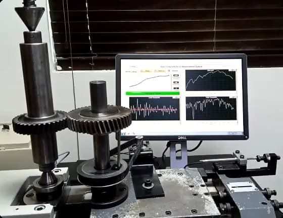
How helical gear axial thrust is established
Start with the tangential force: for a preliminary check, Ft ≈ 2T/d, where T is torque and d is pitch diameter in consistent units. For a helical gear with helix angle β, use Fa ≈ Ft × tan β as the axial-force estimate. The radial component and the exact force directions depend on the selected geometry and convention, so a full gear-force calculation should identify the pressure angle and reference plane.
Axial thrust is a system load. Bearings, shoulders, preload, shaft stiffness and housing stiffness all influence whether the mesh stays aligned. A higher helix angle can improve overlap and smoothness, but it also increases the axial component. The PairGears technical blog provides broader gear-design context; use the drawing and load spectrum for the final calculation.
Example and decision check
If 200 N·m is transmitted through a 100 mm pitch-diameter helical gear, Ft is about 4,000 N. At β = 20°, the preliminary axial estimate is about 4,000 × tan 20° ≈ 1,460 N. This is an illustration only: real bearing reactions also depend on mesh direction, pressure angle, load reversals, efficiency, support spacing and the companion gear.
Are you looking for a reliable manufacturer of down home textile products?
We can quickly provide customers with market analysis, technical support and customized services.- *Name
- Phone
- *Title
- *Content