
What is the mounting distance of a bevel gear?
What is the mounting distance of a bevel gear?
For an intersecting-axis bevel gear pair, mounting distance locates each gear axially from a specified locating surface to the intersection of the gear axes. The locating surface and distance must come from the gearset drawing. This dimension positions the teeth relative to the mating gear and affects the intended tooth contact and backlash; it is not simply the gear's overall length.
Which surfaces define the dimension?
Read both ends of the dimension on the drawing. One end is the specified gear locating face or datum; the other is the axis-intersection reference for the bevel pair. Do not substitute a convenient outer face unless it is the stated datum.
Each member has its own mounting distance. Unequal-size gears need not have equal values, and the housing, shoulders and bearings must locate both members accordingly.

Example: a correct part in the wrong axial position
Suppose the drawing specifies 50.00 mm from a locating face to the axis intersection. An assembled value of 50.20 mm differs by 0.20 mm. Whether that deviation is acceptable depends on the drawing tolerance and gearset requirements; the example is not a recommended tolerance.
Check the bearing position, seating faces and any shims against those datums. A correct outside diameter or overall length does not prove that mounting distance is correct.
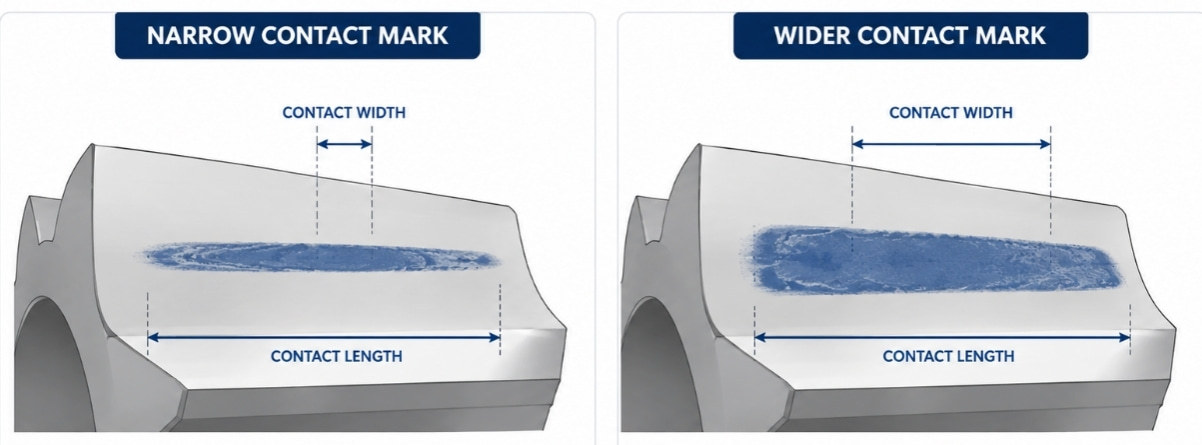
What should be checked after positioning?
Verify the agreed backlash and tooth-contact pattern with the bearing and load conditions recorded. If the results are wrong, review the setup and matching parts before changing the axial position. Hypoid gears have offset axes and require their own defined mounting references.
The PairGears contact-pattern guide explains why the mark must be interpreted together with mounting distance and backlash.
Are you looking for a reliable manufacturer of down home textile products?
We can quickly provide customers with market analysis, technical support and customized services.- *Name
- Phone
- *Title
- *Content