
How do rack-and-pinion gears transmit force and motion?
How do rack-and-pinion gears transmit force and motion?
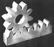
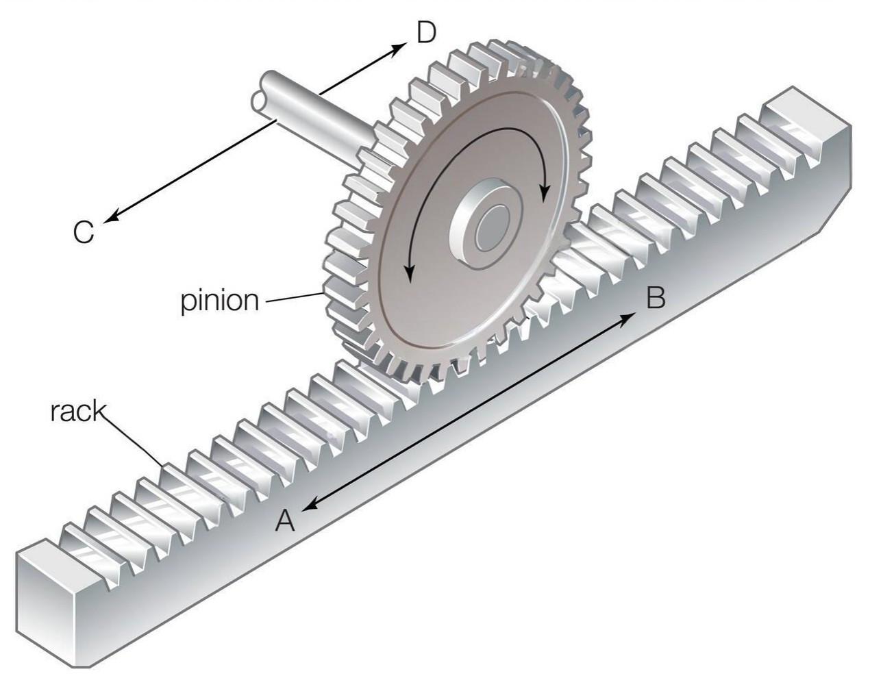
A rack-and-pinion drive converts rotation into straight-line movement through meshing teeth. Pinion torque produces a tangential force that pushes the rack, while pinion speed determines linear speed. If the rack is fixed, the pinion carriage can travel instead. Pitch geometry sets the motion relationship; tooth strength, supports, lubrication and operating loads determine whether the drive can carry the required force.
Follow the motion at the pitch line
The rotating pinion engages successive rack teeth. For a straight-tooth pair, the pinion and rack need compatible module and pressure angle. Guides constrain the rack or carriage so that the mesh remains in position.
At the pitch line, linear speed is v = ωr, with angular speed ω in radians per second and pitch radius r in meters. One pinion revolution gives travel πd. Use the pitch diameter d, not the outside diameter across the tooth tips.
Convert pinion torque into rack force
Ignoring losses, rack force F = T/r = 2T/d. T is the torque at the pinion shaft in N·m and d is in meters. For a 40 mm pitch diameter and 10 N·m at the pinion, the ideal tangential force is 500 N.
At 60 rpm, that pinion advances the rack about 125.7 mm per revolution, or 7.54 m/min. Losses reduce available force; this arithmetic does not establish a permissible tooth load. Motor torque must first be converted through any upstream reducer.
Check the complete linear axis
A horizontal 100 kg load does not automatically require 981 N of rack force. Required force depends on acceleration, guide friction, process resistance and any incline. Add the effects of rotating inertia and starting resistance when sizing the drive.
Check tooth bending and surface capacity, mounting rigidity, backlash, lubrication and the forces tending to separate the mesh. The PairGears rack-and-pinion guide illustrates the mechanism in steering; its application details are not a load rating for a machine axis.
Are you looking for a reliable manufacturer of down home textile products?
We can quickly provide customers with market analysis, technical support and customized services.- *Name
- Phone
- *Title
- *Content