
How do I choose spur gear tooth counts for a required ratio?
How do I choose spur gear tooth counts for a required ratio?
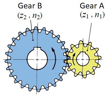
For one external spur gear pair, define the reduction ratio as input speed divided by output speed, then choose integer tooth counts satisfying i = z2/z1. The ratio alone leaves many possible pairs. Use the available center distance and module to narrow the choice, then check tooth geometry, strength, contact, mounting and the permitted ratio error.
State which gear drives and how exact the ratio must be
Let z1 be the input pinion tooth count and z2 the driven gear tooth count. Using positive speed magnitudes, i = n1/n2 = z2/z1. An external pair reverses rotation direction. For a 3:1 reduction, 20/60 and 24/72 teeth give the same nominal ratio but different sizes at the same module.
Specify whether the target is exact or has an allowed error. For an approximate candidate, calculate the actual ratio from its integer tooth counts and compare it with that allowed range. Rounding a calculated tooth count without recalculating the ratio changes the design.
Combine the ratio with the center-distance constraint
For an unshifted standard external spur pair at its reference center distance, a = m(z1 + z2)/2. Therefore z1 = 2a/[m(1 + i)] and z2 = i × z1. Here a and module m use consistent length units. These equations do not replace the working-center-distance calculation for a profile-shifted pair.
Example: with m = 2 mm, a = 80 mm and i = 3, the sum is 80 teeth, giving z1 = 20 and z2 = 60. If a is instead 75 mm, the same assumptions give 18.75 and 56.25 teeth, so no exact integer solution exists under all three constraints. Review module, center distance, permitted ratio error or a properly calculated alternative geometry.

Validate the candidate before releasing the drawing
Check undercut and interference, contact ratio, tooth-root and surface capacity, face width, material, lubrication and the duty cycle. Verify the bore and hub space as well as the outside diameters. Profile shift can alter geometry and working center distance; it does not change the ratio of a fixed pair of tooth counts.
The 20/60 calculation establishes geometry only, not a load rating. Submit the candidate pair with torque, speed, life and accuracy requirements. The PairGears gear drawing checklist helps carry the chosen tooth counts and their operating requirements into manufacturing review.

Are you looking for a reliable manufacturer of down home textile products?
We can quickly provide customers with market analysis, technical support and customized services.- *Name
- Phone
- *Title
- *Content