What Is a Crown Gear and How Does It Relate to Bevel Gears?
A crown gear is a special type of bevel gear with a 90° pitch angle, which gives it a flat pitch surface perpendicular to its axis. It is commonly discussed as the bevel gear equivalent of a rack in spur gearing and can work with a mating bevel pinion in a specific angular gear arrangement.
Although crown gears belong to the bevel gear family, they are not identical to conventional bevel gears or face gears. The term can also be confused with crown wheels used in automotive differentials. For engineers and buyers sourcing precision gear components, understanding these differences helps prevent incorrect gear selection. At PairGears, identifying the correct gear geometry is an important starting point for custom and replacement gear projects.
What Is a Crown Gear?
A crown gear is a bevel gear whose pitch angle is 90°. In conventional bevel gear geometry, the pitch surface is conical. When the pitch angle reaches 90°, the theoretical pitch cone becomes a flat plane perpendicular to the gear axis.
Its teeth are arranged around the gear face, creating a structure that looks different from a conventional bevel gear with a tapered body.
The main characteristics of a crown gear include:
90° Pitch Angle
This is the defining geometric feature.
Flat Pitch Surface
The theoretical pitch cone becomes a plane.
Radial Tooth Arrangement
Teeth are distributed around the gear face.
Bevel Gear Relationship
It can mesh with a compatible bevel pinion.
Rack Equivalent
In basic gear theory, it corresponds to the rack used in spur gearing.
A crown gear is also used as a basic reference member in defining bevel gear tooth proportions and in certain bevel gear generating systems. It should therefore be identified by its pitch geometry rather than simply by its external appearance.
How Does a Crown Gear Relate to Bevel Gears?
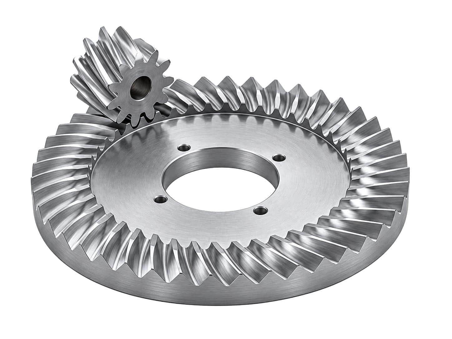
A crown gear is a special case within the broader family of bevel gears. The main difference between a crown gear and a conventional bevel gear is the pitch angle and the resulting pitch surface.
| Feature | Crown Gear | Conventional Bevel Gear |
|---|---|---|
| Pitch angle | 90° | Generally below 90° |
| Pitch surface | Flat plane | Conical surface |
| Gear geometry | Special bevel gear geometry | Conical gear geometry |
| Mating component | Compatible bevel pinion | Mating bevel gear |
| Main design consideration | Planar pitch geometry | Pitch cone geometry |
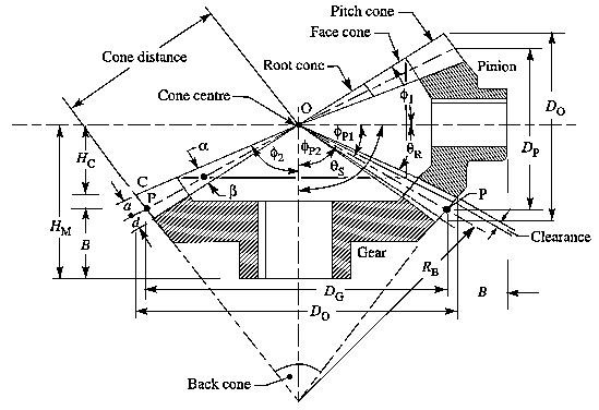
For a pair of external bevel gears, the shaft angle equals the sum of the two mating gears' pitch angles.
Important distinction: A crown gear's 90° pitch angle does not mean that the complete gear pair must have a 90° shaft angle. The pinion geometry also determines the final shaft arrangement.
The tooth form can also vary according to the design. Straight, spiral, and other bevel tooth forms are selected according to the intended gear geometry and manufacturing requirements.
Crown Gear vs. Face Gear vs. Crown Wheel
These three terms can appear in similar mechanical discussions, but they do not always describe the same gear structure. Understanding their differences is useful when reading engineering drawings, searching for replacement components, or communicating with a gear manufacturer.
Crown Gear
Bevel gear with a 90° pitch angle and planar pitch surface. Its typical mating component is a bevel pinion.
Face Gear
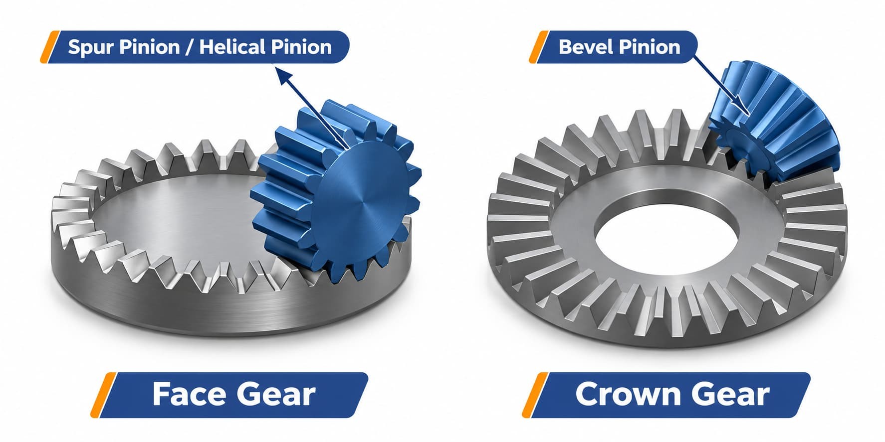
Gear with teeth arranged on a planar face and specially generated tooth geometry. It is generally designed to mesh with a cylindrical spur pinion.
Crown Wheel
Common drivetrain term for a larger driven gear in a final-drive or differential assembly. It typically works with a drive pinion.
Crown Gear vs. Face Gear
Both crown gears and face gears have planar pitch surfaces, but their tooth geometry and mating components are different.
A crown gear is based on bevel gear geometry and is the equivalent of a rack in spur gearing. A face gear is generally designed to mesh with a cylindrical spur pinion.
Face gears are generated using a cutter that represents the mating pinion, allowing the resulting tooth surfaces to work together as a conjugate pair. Although their appearance may be similar, their design and manufacturing requirements should not be treated as interchangeable.
Crown Gear vs. Crown Wheel
In automotive and drivetrain applications, the term crown wheel commonly refers to the larger driven gear in a ring-and-pinion assembly, particularly in a differential or final drive.
Depending on the application and terminology used, a crown wheel may have different bevel gear tooth forms, including spiral bevel or hypoid geometry. Therefore, buyers should not assume that every component called a crown wheel has the specific 90° pitch geometry of a crown gear. The original drawing and mating gear specifications are more reliable than the product name alone.
How Does a Crown Gear Mesh With a Bevel Pinion?
A crown gear works with a compatible bevel pinion to transfer rotary motion. Both gears must have suitable tooth geometry and mounting positions to maintain the intended meshing relationship. Several factors need to be considered during design and assembly.
Pitch Geometry
The pitch angles of both gears determine the shaft arrangement. The mating pinion must be designed to match the crown gear and the required shaft angle.
Tooth Count and Gear Ratio
The tooth count of each member determines the transmission relationship. The gear ratio must be checked together with the required speed and torque.
Mounting Position
The relative positions of the two gears affect tooth engagement. Incorrect mounting dimensions can change the contact position and operating clearance.
Tooth Contact
The contact area shows how the two gears engage under a defined checking condition. Its position and shape should be reviewed together with mounting distance, backlash, and the condition of the mating gear.
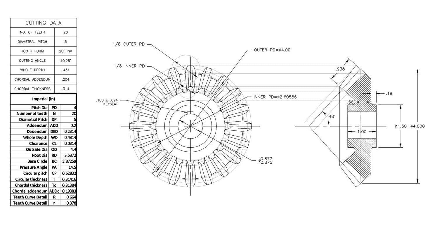
For buyers: A crown gear should be evaluated as part of a complete gear pair rather than as an isolated component. Checking only the outside diameter or tooth count is not enough to confirm compatibility.
Where Are Crown Gears Used?
Crown gears have an important role in bevel gear theory and specialized gear manufacturing systems. One established application is their use as basic generating members in certain bevel gear generators. In this context, the crown gear provides a reference geometry for defining or generating the tooth form of a mating bevel gear.
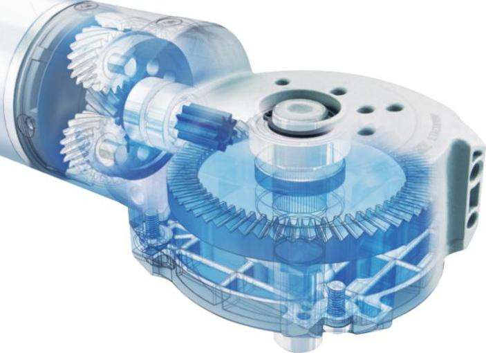
In practical transmission design, crown gear geometry can also be used in specialized angular gear arrangements where the pitch angles and shaft angle meet the required design conditions.
However, not every angular transmission requires a crown gear. Other bevel gear designs may be more suitable depending on the shaft arrangement, torque, rotational speed, installation space, and manufacturing requirements.
Straight Bevel Gears
Used in relatively simple angular transmission arrangements.
Spiral Bevel Gears
Have curved teeth and are commonly selected for applications requiring gradual tooth engagement.
Hypoid Gears
Used when the transmission design requires offset shaft axes.
Zerol Bevel Gears
Provide another tooth geometry option for specific angular transmission requirements.
The correct selection depends on the complete transmission design rather than the appearance of an individual gear.
What Should Buyers Check Before Sourcing a Crown Gear?
When sourcing a crown gear or a replacement gear set, buyers should confirm the gear geometry and mating requirements before requesting production. The following information is useful for an initial technical review.
| Item | Information to Confirm |
|---|---|
| Gear identification | Crown gear, face gear, or crown wheel. |
| Mating component | Bevel pinion specifications. |
| Tooth count | Number of teeth on both gears. |
| Gear ratio | Required transmission ratio. |
| Tooth data | Module or DP, pressure angle, and tooth geometry. |
| Installation | Shaft angle and mounting dimensions. |
| Material | Original material or approved alternative. |
| Heat treatment | Required hardness and case depth, if applicable. |
| Inspection | Tooth geometry, contact pattern, runout, and key dimensions. |
A complete engineering drawing is the best starting point because it provides the geometric and dimensional information needed for evaluation.
If the original drawing is unavailable, buyers can also provide:
For replacement projects, the condition of the mating pinion should also be checked. A new gear may not work correctly with an existing worn or incompatible component.
Providing complete information at the beginning helps reduce repeated technical clarification and the risk of incorrect part identification.
FAQ About Crown Gears
Is a Crown Gear a Type of Bevel Gear?
Yes. A crown gear is a special form of bevel gear with a 90° pitch angle. Its theoretical pitch surface is flat rather than conical.
Does a Crown Gear Always Operate With a 90° Shaft Angle?
No. The shaft angle depends on the sum of the pitch angles of both mating gears. A crown gear's 90° pitch angle does not mean that the complete gear pair must have a 90° shaft angle.
What Is the Difference Between a Crown Gear and a Face Gear?
A crown gear is based on bevel gear geometry and corresponds to a rack in spur gearing. A face gear is generally designed to mesh with a cylindrical spur pinion. Their tooth geometry and generation methods are different.
Is a Crown Wheel the Same as a Crown Gear?
Not necessarily. Crown wheel is commonly used in automotive and drivetrain applications to describe the larger driven gear in a differential or final-drive assembly. The exact geometry should be confirmed from the drawing.
Can a Crown Gear Be Custom Manufactured?
Custom manufacturing depends on the required tooth geometry, mating pinion, engineering drawings, material, and inspection requirements. Buyers should provide a drawing, physical sample, or sufficient technical information for an initial evaluation.
Conclusion
A crown gear is a special form of bevel gear defined by its 90° pitch angle and flat theoretical pitch surface. Its relationship with a mating bevel pinion determines the actual transmission geometry, including the shaft angle. Understanding this structure also helps distinguish crown gears from face gears and conventional bevel gears.
For buyers sourcing custom or replacement gear components, identifying the correct gear type is only the first step. Tooth count, mating pinion specifications, tooth geometry, material, and mounting dimensions should also be checked to ensure that the selected components meet the requirements of the transmission system.
Looking for a Crown Gear or Custom Bevel Gear?
If you are sourcing a crown gear, bevel gear, or a related replacement component, PairGears can help review your project requirements. Send your engineering drawing, sample photographs, or OEM number to discuss your project and request a quotation.