
What is gear transmission?
Gear transmission transfers motion and power through meshing gear teeth. Depending on the arrangement, it changes rotational speed, torque or direction, or converts rotation into linear travel with a rack. The tooth counts set the ideal speed relationship. Actual performance also depends on tooth geometry, alignment, lubrication, load and losses in the complete drive.
How gear transmission changes motion
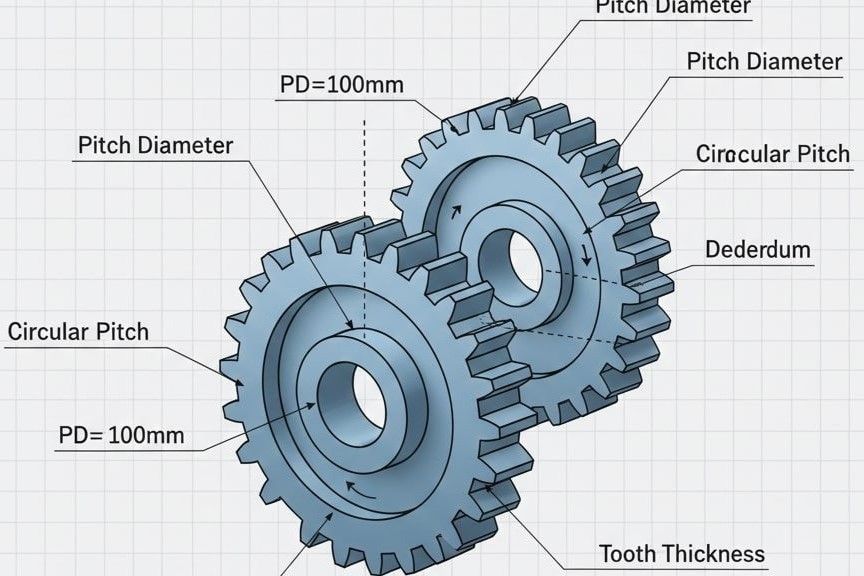
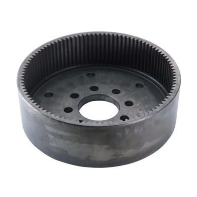
A driving gear pushes the teeth of its mating gear. In a simple fixed-axis pair, the ratio is determined by tooth counts. An external pair turns in opposite directions; an external pinion meshing inside an internal gear turns in the same direction.
- Parallel shafts: spur or parallel-axis helical gears.
- Intersecting shafts: bevel gears.
- Nonparallel, nonintersecting shafts: arrangements such as worm drives.
- Linear travel: a pinion drives a rack.
A simple 3:1 reduction example
For a fixed-axis pair with a 20-tooth driver and a 60-tooth driven gear:
i = 60 ÷ 20 = 3
At 900 rpm input, output speed is 300 rpm.
Ignoring losses, output torque is three times input torque. In practice, output torque is input torque × ratio × efficiency. This example is illustrative, not a PairGears performance rating.
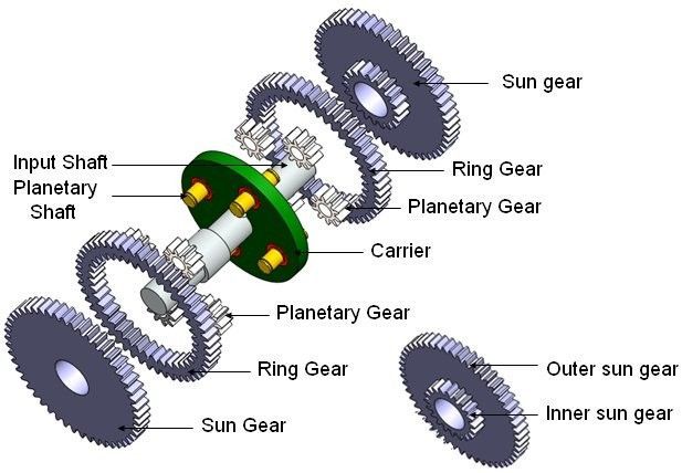
Do not apply this two-gear formula directly to a planetary set without identifying its operating arrangement.
What to specify for a working gear pair
Give PairGears the shaft layout, input speed, output torque, duty cycle, target ratio, available space and mating-part drawing. Geometry and mounting must be compatible; ratio alone does not establish load capacity.
Review the planetary transmission gear checklist for a compound assembly.
Related questions
Are you looking for a reliable manufacturer of down home textile products?
We can quickly provide customers with market analysis, technical support and customized services.- *Name
- Phone
- *Title
- *Content