
How can I reduce wear in crossed-helical screw gears?
How can I reduce wear in crossed-helical screw gears?
Reduce screw-gear wear by identifying the damage mechanism before replacing parts. Check lubrication, contamination, shaft geometry, bearing support and the mating materials against the actual load and speed. Crossed-helical gears have localized contact and substantial sliding, so a pair that fits geometrically can still be overloaded. Correct the cause, then validate the replacement pair under representative operating conditions.
Record the damage and operating conditions
Inspect both gears and retain photographs of the contact areas. Record speed, transmitted torque, duty cycle, temperature, lubricant and any recent changes. Polishing, abrasive scratches, scoring and pitting are different observations; do not assume that every damaged surface simply needs a harder gear.
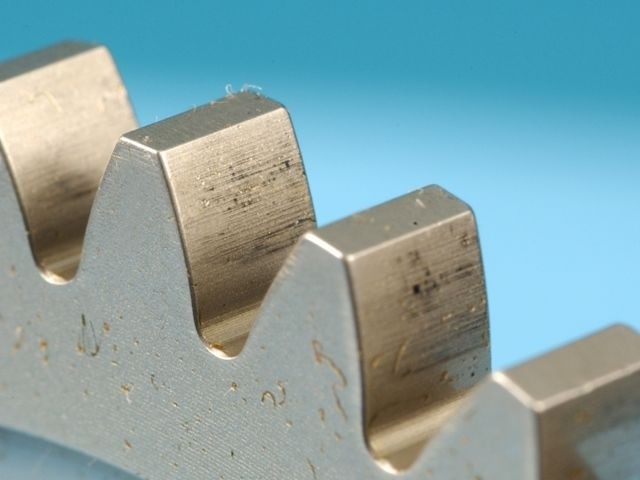
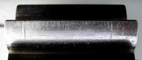
The PairGears gear-failure overview helps organize the inspection. The photographs here illustrate general tooth damage, not a diagnosis of a specific screw-gear installation.
Check the sliding contact and material pair
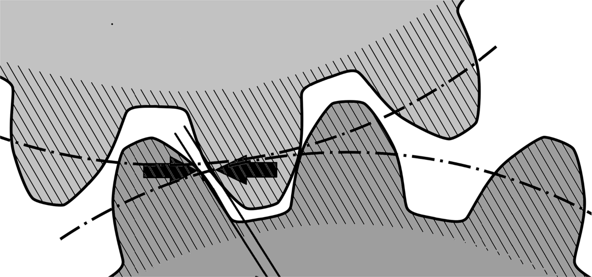
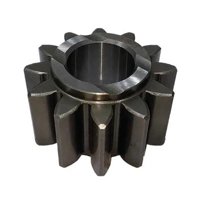
Crossed-helical screw gears run on nonparallel, nonintersecting shafts. Their localized contact and sliding make surface durability and lubrication important selection limits. Verify the lubricant type, viscosity, delivery and cleanliness for the material combination and operating temperature.
Review both materials and their surface condition together. Some same-material combinations are susceptible to adhesive wear or scoring; a compatible dissimilar pair may help, but must still meet the load and wear requirements. Changing hardness alone does not establish a suitable pairing.
Verify geometry, support and capacity before restarting
Check normal module, normal pressure angle, helix angles and hands, shaft angle and center distance against the paired design. Inspect bearings and shaft restraint, including the support for axial forces. Confirm the specified contact position and backlash; tightening the mesh to remove noise can make conditions worse.
If rapid wear persists after installation and lubrication are corrected, recalculate surface durability for the actual speed and load. A different size, material pair or transmission arrangement may be needed. Replace damaged members as an assessed pair where required, then monitor temperature and wear during a controlled trial.
Are you looking for a reliable manufacturer of down home textile products?
We can quickly provide customers with market analysis, technical support and customized services.- *Name
- Phone
- *Title
- *Content