
Can a worm gear pair be designed to self-lock?
Can a worm gear pair be designed to self-lock?
A worm gear pair can resist being driven backward by the wheel when its lead angle and friction conditions permit self-locking. A high reduction ratio alone does not guarantee this behavior. Lubrication, temperature, wear and vibration can change the result. Verify the complete drive under its operating conditions, and use a suitably rated holding device where unintended motion could release a load.
Start with lead angle and friction
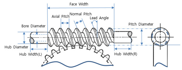
A smaller worm lead angle generally makes backdriving more difficult. Whether the wheel can drive the worm also depends on friction at the tooth contact. That friction is affected by the material pair, surface condition and lubricant. Ratio is only an indirect clue: two designs with the same ratio can have different lead angles.
Ask the designer to assess the actual geometry and expected friction range. Do not apply a single lead-angle cutoff to every worm set or copy a catalogue claim to a different material and lubricant combination.
Keep lubrication and service conditions in the assessment
Evaluate starting, running, warm operation and the expected wear state. Shock or vibration can overcome resistance that appeared adequate in a quiet static test. Static self-locking does not establish the ability to stop a moving load.
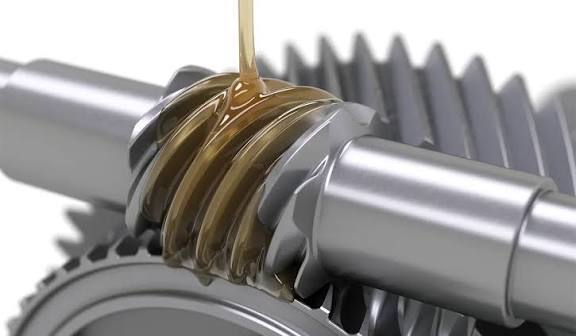
Do not starve the mesh of lubricant to increase friction. Use the specified lubrication and reassess holding behavior if oil, materials or surface finish change. The PairGears worm-drive efficiency guide explains the related geometry and friction considerations.
Specify how the machine must hold the load
Describe the load direction, maximum torque, duty, vibration and acceptable movement to the drive supplier. Request a documented assessment for those conditions and an appropriate validation plan. A bench test at one temperature is not evidence for every service condition.
For example, a positioning table may need a defined resistance to reverse motion, whereas a suspended load needs a rated load-holding arrangement. Select a suitable brake or other holding device for the latter; a worm pair described as self-locking should not be treated as a brake specification.
Are you looking for a reliable manufacturer of down home textile products?
We can quickly provide customers with market analysis, technical support and customized services.- *Name
- Phone
- *Title
- *Content