
How do you calculate the perimeter of a spur gear?
How do you calculate the perimeter of a spur gear?
First define which perimeter you need. The reference pitch-circle circumference is πd = πmz, where m is module and z is tooth count. The tooth-tip circle has circumference πda, using the actual outside diameter da. Neither value is the full length around every tooth and root. That toothed outline must be calculated from the specified profile or measured in CAD.
Calculate the reference pitch circumference
For a spur gear, reference diameter d = mz. Its reference circumference is C = πmz. With module 2 mm and 30 teeth, d = 60 mm and C ≈ 188.50 mm. Circular pitch is the distance between corresponding adjacent tooth positions along that circle: p = C/z ≈ 6.283 mm.
The reference circle is a geometric construction, not a physical edge to trace with a tape. State millimeters or inches consistently when reporting the result.
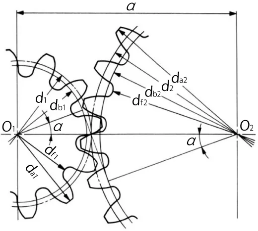
Use the actual tip diameter for the outside circle
For a standard, unshifted, full-depth spur gear with addendum m, da = m(z + 2). The same module-2, 30-tooth example has da = 64 mm, giving an outside-circle circumference of about 201.06 mm. This is a circle through the tooth tips, not the contour through the spaces between them.
Profile shift, nonstandard addendum and tip modifications can change the outside diameter. Use the drawing’s actual da rather than applying m(z + 2) to every gear. The PairGears spur-gear parameter guide explains the wider design context.
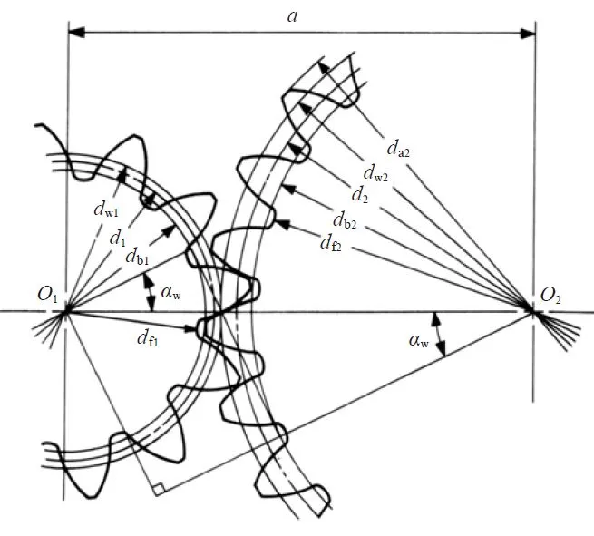
Measure the complete tooth outline when that is required
For a planar external outline, add the lengths of all tooth flanks, tip arcs, root sections and fillets. In CAD, select the closed outer contour in a transverse section; exclude the bore unless a separate total-boundary length is requested. Do not sum every edge of a three-dimensional solid.
Module and tooth count alone cannot define this exact contour length. Pressure angle, profile shift, tooth thickness, root geometry and modifications affect it. For a cutting-path estimate, also account separately for tool compensation, lead-ins and any additional cuts.
Are you looking for a reliable manufacturer of down home textile products?
We can quickly provide customers with market analysis, technical support and customized services.- *Name
- Phone
- *Title
- *Content