
How can you minimize backlash in a compound spur gear train?
How can you minimize backlash in a compound spur gear train?
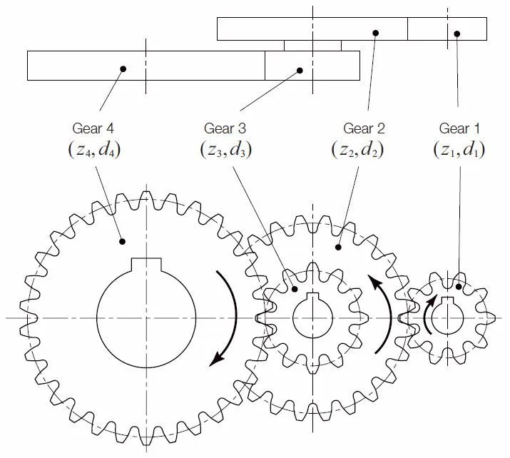
Minimize backlash in a compound spur gear train by assigning a lost-motion budget to each mesh, converting every contribution to the same output shaft, and controlling gear and mounting errors. Prioritize the stages that contribute most at the output. Reduced-clearance or split-gear designs can help, but the complete assembly must still turn freely under its intended operating conditions.
Refer every stage to the same shaft
Angular clearances measured on different shafts cannot simply be added. For a two-stage reduction, let b1 be the first mesh’s angular backlash at its driven shaft and b2 the second mesh’s angular backlash at the final output. If the second stage reduces speed by i2, the ideal unloaded output backlash is approximately b1/i2 + b2.
For example, b1 = 0.20°, b2 = 0.05° and i2 = 4 give 0.10° at the output. Halving b1 saves 0.025°; halving b2 also saves 0.025°. This illustrative calculation excludes bearing play, loose connections and elastic deflection.
Choose an adjustment that suits the duty
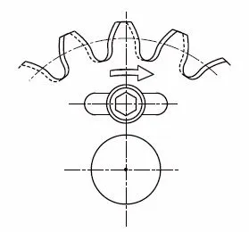
Specify tooth thickness and operating center distance together. Low runout helps keep clearance consistent through a revolution. A split gear can reduce free movement by setting the angular phase of its two halves; a spring-loaded design requires a separate preload and load-capacity assessment.
Simply forcing standard gears closer together may create tight spots. Check contact, friction and temperature over the operating range. The PairGears spur-gear backlash guide gives the single-mesh context for this stage-by-stage budget.
Verify total reversal motion on the assembly
Hold the input at a defined position and measure output movement while reversing a small, specified test torque. Repeat at several gear positions. Record temperature, lubrication and test torque so that later measurements are comparable.
Compare the result with the output budget, then inspect individual meshes and shaft connections if it exceeds the limit. Loaded reversal also includes torsional compliance, so distinguish tooth clearance from deformation. A motor-side encoder alone cannot directly measure every source of downstream lost motion.
Are you looking for a reliable manufacturer of down home textile products?
We can quickly provide customers with market analysis, technical support and customized services.- *Name
- Phone
- *Title
- *Content