What Are Internal Gears and Where Are They Used?
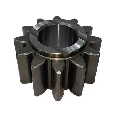
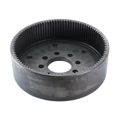
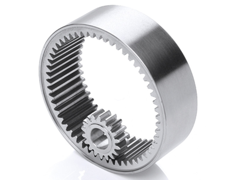
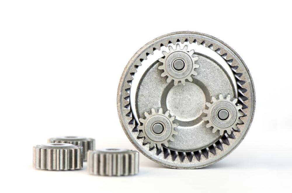
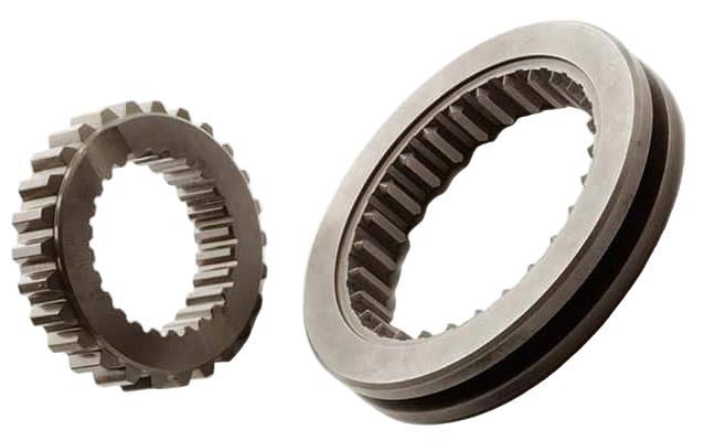
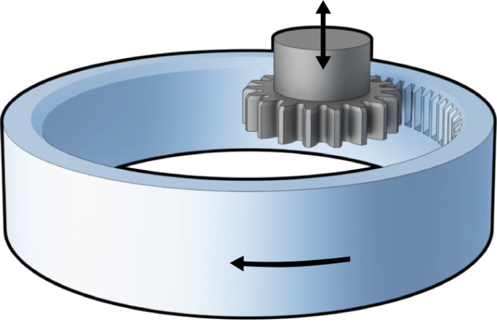
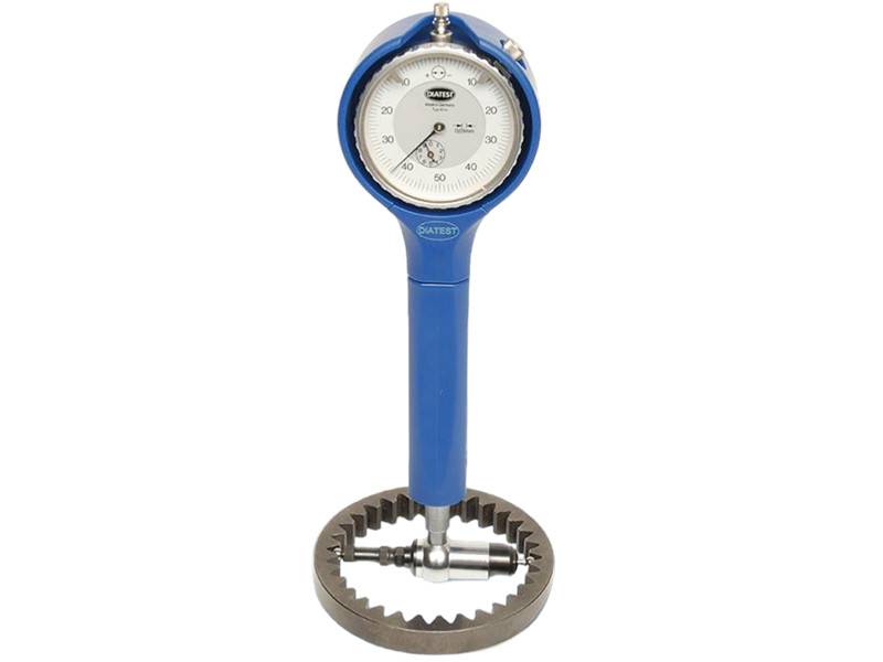
Internal gears appear in many compact drive systems. Their teeth are cut on the inside of a cylindrical ring, so they mesh with an external gear positioned within that ring. At PairGears, internal gear projects are commonly reviewed for agricultural machinery, heavy-duty trucks, construction equipment and electric vehicles. The basic concept is simple, but gear geometry, mating-pinion data, heat treatment and inspection still need to match the application. An internal gear is a cylindrical gear with teeth cut on its inner surface. It usually meshes with an external pinion located inside the gear. In a simple internal gear pair, both gears normally rotate in the same direction. Internal gears are often used as ring gears in planetary arrangements because they allow a compact, coaxial layout. An internal gear is a ring-shaped component with teeth formed around its inside diameter. In planetary arrangements, it is often called an internal ring gear or an annulus gear. The gear normally meshes with one or more smaller external gears. Instead of sitting beside the mating gear, as two external gears would, the external gear runs inside the internal gear. Common forms include: Straight internal teeth are used where the project requires a compact cylindrical gear arrangement. Angled internal teeth may be selected when the complete drive design requires helical meshing. Internal ring gears surround the planet gears in many planetary arrangements. The right type depends on the required speed, torque, noise level, installation space and manufacturing accuracy. Tooth contact takes place inside the ring gear. In a simple pair made up of one internal gear and one external pinion, the two gears generally turn in the same direction. Two external gears normally turn in opposite directions. The arrangement becomes more complex in a planetary gear system. A typical system includes: A central external gear positioned at the center of the system. Several external gears that mesh with the sun and the internal ring gear. The structure that supports and positions the planet gears. The outer ring with teeth on its inner diameter. System-level review: Speed ratio and rotation direction depend on which member is fixed and which members act as the input and output. The internal gear is only one part of the system, so its effect cannot be judged without reviewing the complete gear arrangement. Internal gears suit compact, coaxial drive layouts. Their geometry also limits tool and probe access, which can make manufacturing and inspection more demanding than for external gears. Internal ring gears may be found in tractor drive assemblies, combine harvester drives and compact final-drive units. These machines often work under changing loads, shock loads, dust and long operating cycles. The material, heat treatment and tooth accuracy therefore need to match the actual duty conditions. Heavy-duty trucks may use internal gears in wheel-end assemblies, selected drive sections and other compact drivetrain systems. Replacement work requires careful identification. The mating gears, equipment version, installation dimensions and original part information should all be checked. Two internal gears can look similar while having different tooth data or mounting references. Excavators, loaders and other construction machines often use internal gears in travel drives, wheel drives and related drive assemblies. The internal gears in these units may carry high torque and repeated load changes. Tooth profile, heat treatment, hardness and alignment with the mating parts can affect load distribution and service life. Internal gears may be used in compact planetary arrangements, e-axles and selected EV drivetrain designs. EV applications often place greater emphasis on drive efficiency, gear noise and dimensional consistency. Not every EV drive design uses an internal gear, so the full drivetrain layout should be reviewed before a gear design is selected. Internal gears can help designers package a drive system within limited space. In planetary arrangements, they also allow the input and output to share the same central axis. Depending on the complete system design, internal gears may support: Supports compact, coaxial drive arrangements. May support large speed ratios in suitable planetary arrangements. Allows the use of several planet gears in the system. Fits enclosed drive structures. Makes practical use of the available drive diameter. Load-sharing note: Several planet gears may share the transmitted load, but equal load sharing is not automatic. Gear accuracy, carrier stiffness, alignment and assembly conditions also matter. The tooth numbers and geometry of the internal gear and mating pinion must work together. An unsuitable combination can cause involute interference, trochoid interference or assembly problems. The cutting tool has to work inside the gear. Tool access is therefore more limited than it is on an external gear. Gear diameter, face width and nearby internal features can all affect the choice of manufacturing process. Carburizing, hardening and other heat-treatment processes can change roundness, pitch accuracy or runout. Production planning should account for expected distortion, machining allowances and the required inspection method. Internal tooth surfaces are harder to reach. Depending on the gear size and accuracy grade, inspection may require suitable probes, dedicated measuring equipment or a functional check with a mating gear. Common manufacturing methods include: A flexible method for producing internal gear teeth under suitable geometry and access conditions. A productive internal gear cutting option when machine capability, rigidity and part geometry are suitable. May be used for suitable high-volume applications where tooling and geometry support the process. May be considered under certain geometry, quantity and manufacturing conditions. May be applied when the geometry and required accuracy allow a suitable finishing route. Process selection depends on the module or diametral pitch, tooth number, pressure angle, helix angle, face width, material, heat treatment, order quantity and required accuracy. The gear name alone is not enough to choose a process. The drawing, mating gear and functional requirements need to be reviewed first. For a broader overview, see the gear manufacturing process. The gear accuracy inspection plan should follow the drawing and the application. It may cover: Checks the tooth profile against the specified geometry. Reviews the tooth direction across the face width. Evaluates tooth spacing consistency around the gear. Checks the relationship between the teeth and the selected datum. Confirms tooth size according to the drawing and method. Checks how the bore datum relates to the tooth geometry. Confirms the material against the agreed project requirement. Checks the specified hardness at the defined test location. May be required for carburized or case-hardened gears. Inspection datum matters: The report should identify the measurement datum and inspection method. A gear can pass individual size checks and still create assembly problems if the teeth are not correctly related to the bore, shaft or mating gear. A detailed drawing is the clearest starting point. For replacement gear projects, buyers may also provide sample photos, an OEM number or a worn component. Measurements taken from a worn gear need careful review because wear may have changed the original tooth geometry. PairGears reviews custom internal gear projects for agricultural machinery, heavy-duty trucks, construction equipment and electric vehicles. The review may cover the drawing or sample, mating gear, installation references, material, heat treatment, manufacturing process, inspection plan and first-article approval before batch production. This helps both sides confirm the technical basis of the project before manufacturing begins. Check the available gear geometry, dimensions and project starting information. Confirm the pinion, mounting references and drive relationship when information is available. Review material, heat treatment and a suitable manufacturing route for the stated requirements. Clarify the inspection plan and approval basis before batch production. Send the drawing, sample information, mating-pinion data, material, heat treatment, quantity and inspection requirements for a project review. Is an internal gear the same as a ring gear? In a planetary arrangement, the ring gear is an internal gear. In other drivetrain applications, “ring gear” may refer to a different component, so the tooth arrangement should always be confirmed. Do internal gears rotate in the same direction? In a simple mesh between an internal gear and an external pinion, the gears usually rotate in the same direction. In a planetary system, the direction depends on which component is fixed, driven or used as the output. Why are internal gears used in planetary systems? The ring gear surrounds the planet gears and helps create a compact, coaxial drive arrangement. Depending on the system layout, it can also support a large speed ratio and several load paths. Are internal gears harder to manufacture? They can be. Cutting-tool access is restricted, interference needs to be checked, heat treatment may distort the ring, and the internal teeth are harder to inspect. What information is needed for an internal gear quotation? A detailed drawing is preferred. Buyers should also provide the mating-pinion information, material, heat treatment, accuracy, inspection requirements, application and order quantity. Internal gears are useful where a drive system must fit within a compact, coaxial layout. This is why they appear in selected gear arrangements for agricultural machinery, heavy-duty trucks, construction equipment and electric vehicles. A successful internal gear project depends on more than tooth count and overall dimensions. The mating gear, interference risk, material, heat treatment, manufacturing process and inspection datum all need to be confirmed before production. If you are reviewing a custom internal gear project, contact us with your drawing, sample information and mating-pinion data. PairGears can use these details for an initial technical review and quotation.Quick Answer
What Is an Internal Gear?
Internal Spur Gears
Internal Helical Gears
Planetary Ring Gears
How Do Internal Gears Work?
Sun Gear
Planet Gears
Planet Carrier
Internal Ring Gear
Internal Gears vs External Gears
Comparison
Internal Gear
External Gear
Tooth position
Inside the gear ring
Outside the gear body
Simple mesh direction
Usually the same direction
Usually opposite directions
Installation
Compact internal arrangement
Side-by-side arrangement
Common systems
Planetary arrangements and compact final drives
General gear trains and open drives
Manufacturing access
More restricted
Generally easier
Inspection access
More difficult inside the gear
More accessible
Where Are Internal Gears Used?
Agricultural Machinery
Heavy-Duty Trucks
Construction Equipment
Electric Vehicles
Why Are Internal Gears Used?
Compact Layout
Speed Ratio
Multiple Planets
Enclosed Structure
Diameter Use
What Are the Limitations of Internal Gears?
Gear Interference
Restricted Machining Space
Heat-Treatment Distortion
More Difficult Inspection
How Are Internal Gears Manufactured?
Gear Shaping
Gear Skiving
Broaching
Specialized Milling
Hard Finishing
How Are Internal Gears Inspected?
Tooth Profile Deviation
Tooth Lead Deviation
Pitch Deviation
Radial Runout
Tooth Thickness
Bore-to-Tooth Datum
Material Verification
Surface Hardness
Effective Case Depth
What Should Buyers Confirm Before Ordering?
Information
What to Provide
Gear geometry
Module or DP, tooth number, pressure angle and helix angle
Main dimensions
Inside diameter, outside diameter, face width and mounting features
Mating gear
Pinion drawing, tooth number and related gear parameters
Material
Required steel grade or approved equivalent
Heat treatment
Carburizing, induction hardening, through hardening or other requirements
Accuracy
ISO, DIN or AGMA grade when specified
Application
Load, speed, duty cycle, lubrication and operating environment
Inspection
Profile, lead, pitch, runout, hardness and certificate requirements
Quantity
Prototype quantity, batch size and estimated annual demand
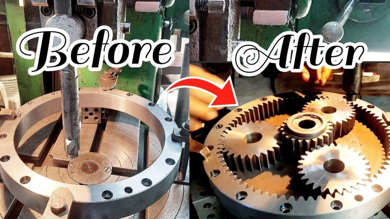
How PairGears Reviews Internal Gear Projects
Drawing or Sample Review
Mating Gear and Installation Review
Material and Process Planning
Inspection and First-Article Approval
Preparing an Internal Gear RFQ?
FAQ
Conclusion
Need a Custom Internal Gear?