
How do I verify that a worm gear pair is installed correctly?
How do I verify that a worm gear pair is installed correctly?
A worm gear pair is installed correctly only when the approved worm and wheel are matched, shaft angle, center distance and wheel position meet the drawing, backlash is measured by the specified method, tooth contact is centered and repeatable, bearings are secure, and lubrication is present. Turn it by hand first, then run it unloaded while checking noise, vibration, temperature and contact.
Locate the matched worm and wheel from drawing datums
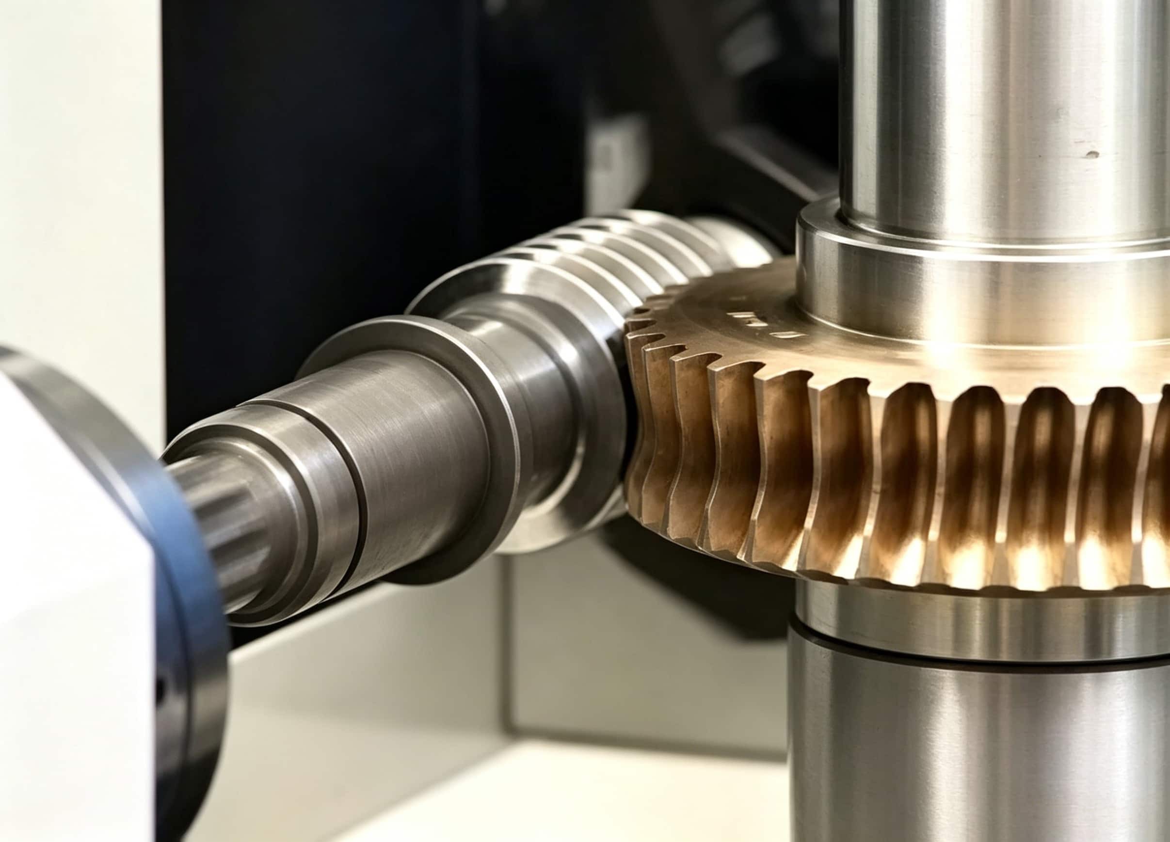
Confirm that the worm and wheel belong to the approved pair: starts, tooth count, module or DP, pressure angle, lead or helix data and hand must match the drawing. Set shaft angle, center distance and axial wheel position from the housing and bearing datums. Do not center the assembly from worn tooth flanks or copy a catalog tolerance from another series.
The PairGears worm-gear assembly-error FAQ explains why allowable offsets are pair-specific. For a custom or replacement set, the approved drawing and housing layout control the setup.
Measure backlash, contact and support conditions together
Measure backlash at the stated position, direction and temperature; a value without the measurement convention is ambiguous. Apply marking compound and rotate through several mesh cycles in both directions. The contact should be repeatable and agree with the approved target rather than crowding one edge. Check worm and wheel runout, bearing seating, shaft endplay, housing looseness and seal drag before blaming the tooth geometry.
Supply the specified lubricant before a powered test. Worm gearing has substantial sliding contact, so oil type, level, delivery and temperature can change noise, wear and measured running behavior. Avoid zero backlash unless the design explicitly provides a controlled adjustment method.
Use a staged start-up and stop on abnormal behavior
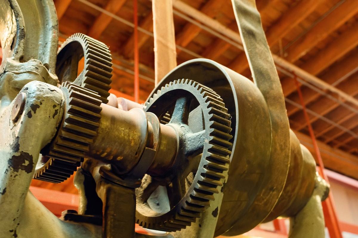
Turn the assembly by hand before power is applied. It should rotate without binding through the full cycle. Then run unloaded at low speed while monitoring noise, vibration, current or torque and temperature. Stop if contact moves to an edge, backlash disappears, temperature rises unexpectedly, or noise and vibration change sharply.
After the initial run, inspect the contact mark and lubricant, recheck fasteners and record the accepted setup. Increase speed and load only under the approved commissioning plan. A successful unloaded spin does not prove load capacity, thermal stability or lubrication performance at duty.

Are you looking for a reliable manufacturer of down home textile products?
We can quickly provide customers with market analysis, technical support and customized services.- *Name
- Phone
- *Title
- *Content