
How is bevel-gear mounting distance tolerance set and verified?
How is bevel-gear mounting distance tolerance set and verified?
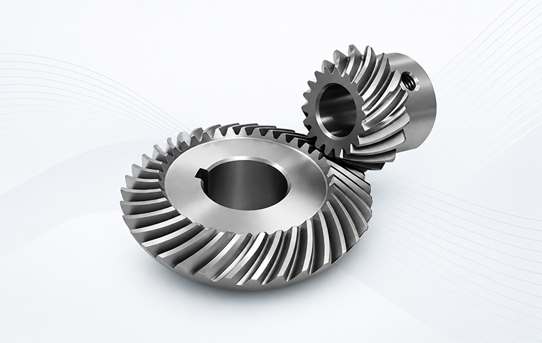
There is no universal bevel-gear mounting-distance tolerance. It is set from the approved gear design, datum scheme, housing and bearing stack, backlash target and acceptable tooth contact. PairGears should place the dimension and tolerance on the controlled drawing, inspect the component datums and runout, then verify the assembled pair through mounting position, shaft angle, backlash and contact-pattern checks.
Use the approved gear-set geometry, not a generic tolerance
Mounting distance locates each bevel gear axially from a defined reference surface to the design position of the tooth system. The allowable variation depends on the matched gear design, tooth bearing sensitivity, ratio, face width, backlash, load, speed and housing stiffness. A tolerance copied from another catalog pair can move contact and backlash outside the intended window.
The PairGears mounting-distance FAQ defines the basic dimension. For production, the controlled drawing should identify the datum, nominal value, tolerance and whether a paired-gear setting or contact target controls final assembly.
Build the tolerance from the complete locating stack
Include the gear blank datum, bore or shaft fit, shoulder position, spacers or shims, bearing seats, bearing internal position, endplay or preload, cover and housing dimensions, shaft angle and any offset. Allocate component tolerances so the worst credible stack still permits the required contact and backlash; use statistical treatment only when the assembly and process controls justify it.
Keep drawing and assembly references consistent. Measuring a gear crown-to-back dimension does not by itself prove the installed mounting distance, because bearing and housing stack errors can shift the gear. Thermal growth, reversible thrust and loaded deflection may also require an operating allowance.

Verify component datums and the assembled tooth contact
Inspect the specified gear datum relationships, axial locating surfaces, bore or shaft, runout and tooth geometry. In the assembly, confirm shaft angle, offset where applicable, axial position, backlash and bearing condition. Apply marking compound under the agreed rotation and light-load method; compare the resulting pattern with the approved target rather than aiming for a visually centered mark without design context.
KHK's bevel-gear application guidance shows that mounting-distance error shifts contact high on one member and low on the other, while angle or offset errors create different patterns. Use that behavior diagnostically, then accept the PairGears set only to its drawing, inspection plan and approved contact criteria.
Are you looking for a reliable manufacturer of down home textile products?
We can quickly provide customers with market analysis, technical support and customized services.- *Name
- Phone
- *Title
- *Content