
What do gear tooth modifications mean?
What do gear tooth modifications mean?
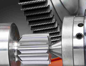
Gear tooth modifications are deliberate, small changes from the nominal involute profile or straight lead. Profile modifications—such as tip or root relief—act from root to tip; lead modifications—such as crowning, end relief or lead slope—act across face width. They are designed for a stated load, speed and alignment to manage contact, transmission error and edge loading, then verified by inspection.
Separate profile and lead modifications
Profile modifications change the flank in the root-to-tip direction. Examples include tip relief, root relief and profile crowning. Lead modifications change the flank across its face width. Examples include lead crowning, end relief and a controlled lead slope. Twist and bias may also be specified, but they need an explicit definition and measurement method.
These are intentional microgeometry features, not accidental profile or lead error. The PairGears lead-crowning FAQ shows why the modification direction and shape must be stated rather than described only as “crowned teeth.”

Design the modification for the loaded system
Under torque, gear teeth, shafts, bearings and housings deflect. A suitable profile relief can reduce unwanted entry or exit contact, while a suitable lead crown or end relief can reduce sensitivity to edge contact from misalignment. The design may also target transmission error, noise or contact-stress distribution.
More modification is not automatically better. Excessive relief can shorten the effective contact area, concentrate load or change behavior across the duty cycle. Set the amount and extent from the actual torque range, speed, temperature, support stiffness, alignment and manufacturing variation. Loaded tooth-contact analysis or another approved engineering method should support critical designs.
Put measurable limits on the drawing and report
Specify the modified flank, direction, shape, start and end positions, amount, reference, tolerance and evaluation range. A note such as “tip relief required” is incomplete if it omits the relief length and magnitude. Agree how the modification will be measured and how datum, filtering and trace presentation will be handled.
Verify profile and lead charts against the modified target, then review tooth contact under the defined assembly and load conditions. An unmodified nominal trace is not the acceptance reference for a deliberately modified flank, and a contact-marking photo alone does not replace dimensional evidence.

Are you looking for a reliable manufacturer of down home textile products?
We can quickly provide customers with market analysis, technical support and customized services.- *Name
- Phone
- *Title
- *Content